
Manual

CTI Products, Inc. NCB-EL/FL User Guide
2. Installation 14
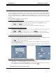
after the cable has been connected. The “
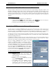
Downloading
” window will be displayed. When
downloading has completed successfully, the “
Sync
” field will change to a green ‘
9
’.
•
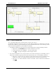
The “
Instructions
” window will prompt to connect the selected COM port to the next NCB
Member. Click
OK
the cable has been connected. Continue this process for all NCB units.
•
When downloading is complete to all members, the “
Channnel
Sync
” indicator will change to a
green ‘
9
’.
C) Exit EtherPlug:
•
From the
File
menu, select
Exit
.
S
TEP
6. P
HYSICALLY
I
NSTALL
NCB
S INTO THE
IP N
ETWORK
A) Select an Ethernet connector:
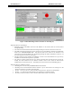
•
OPTION switches are used to select the active Ethernet connector. Use the 10BaseT setting for the
NCB-Etherlon and the AUI setting for the NCB-Fiberlon. The position of the OPTION switches
are read by the NCB module at power-up or after pressing the “RESET” button on the front panel.
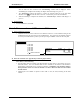
12345678
ON
1. Not Used
2. Not Used
3. Not Used
4. Not Used
5. Not Used
6. Not Used
7.
8.
Modem Mode Switch: 7 8
10BaseT
UP UP
AUI (Fiber)
DN DN
X = Don’t Care
Ethernet Connector
B) Mount the NCB units (See Appendix B for Mounting Option details):
Desk, Wall, or Rack Mounting
•
Non-slip rubber feet are included on all NCB modules to allow them to conveniently rest on any
horizontal surface. Four 6-32 threaded holes are also available on the bottom of the module to
allow bolting of the module in any convenient orientation.
WARNING: Care should be taken to
limit protrusion of the screw into the module to no more than 0.125 inch from the module
bottom surface!
•
Mounting kits are available as options to allow wall or rack (19” EIA) mounting of the NCB
module.