
Manual

CTI Products, Inc. NCB-EL/FL User Guide
Appendix C. Connector Details 26
A
PPENDIX
C. C
ONNECTOR
D
ETAILS
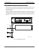
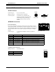
DC IN Connector
Connector type: 2.5 x 5.5 mm coaxial
Mating Connector: Switchcraft 760 or equivalent
Connector pinout: CTI Products, Inc. standard power
supply is wired with center pin positive,
NCB module can accept either pin
positive, polarity routing is provided
internal.
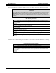
NETWORK Connectors
RJ-45 Connectors:
Pins 1 and 2 of both RJ-45 connectors as well as the screw-terminal connector
are all wired in parallel. The dual RJ-45 connector designates "IN" and "OUT".
These designations apply only to DC power that is passed down unused pairs of
the 4 pair network cable. The two pins carrying the network pair are straight-
through.
Connector Type: Standard RJ-45 telephone connector, 8 position 8
contact.
Pin Function Notes
1 Network Network connection is NOT polarity sensitive
2 Network Pins 1,2 of IN and OUT connectors tied parallel
3 No Connection Pin 3 of IN and OUT connectors tied together
4 No Connection Pin 4 of IN and OUT connectors tied together
5 No Connection Pin 5 of IN and OUT connectors tied together
6 No Connection Pin 6 of IN and OUT connectors tied together
7 No Connection Pin 7 of IN and OUT connectors tied together
8 No Connection Pin 8 of IN and OUT connectors tied together
2-Position Screw-Terminal:
Mating Connector: Weidmuller 128176
Pin Function
1Network
2Network
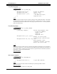
+-
Polarity
DC IN
Front View
NETWORK OUTIN
12345678
NETWORK
1 2