
Manual


CTI Products, Inc. NCB-EL/FL User Guide
Appendix F. IP Addresses 35
When a message is destined for an IP address whose MAC address has not yet been resolved, an ARP
REQUEST is sent from the local host as a broadcast message, asking for MAC identification. A remote host
with the IP address in question generates an ARP RESPONSE. This ARP RESPONSE contains the requested
MAC address. The local host receives the message, and places the IP Address and the matching MAC Address
in its ARP Cache. The original message is then sent using the MAC Address found previously. Any additional
messages to this remote IP address will be sent using the MAC address found in the local host’s ARP cache.
Ethernet 10BaseT Cables
When connecting two IP devices together, either a straight-through cable or a crossover cable may be required.
If interconnecting similar devices, then a crossover cable is needed. Examples would be interconnecting two
NCB routers, or two IP routers, or two hubs, or two computers. Generally, if the two devices are both Layer 3
devices, then a crossover cable is required. Routers operate at Layer 3. Similarly, if the two devices are Layer
1 or 2 devices, they would also require a crossover cable. Bridges, switches, and Network Interface Cards
(NIC) operate at Layer 2, and hubs, repeaters, and concentrators operate at Layer 1.
If interconnecting dissimilar devices, then a straight-through cable is needed. Dissimilar devices would involve
one Layer 3 device and a Layer 1 or Layer 2 device.
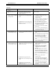
The following table summarizes devices in each layer.
Layer 3 Layer 2 Layer 1
IP Router Bridge Hub
NCB Router Switch Repeater
NIC Concentrator
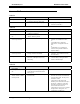
The following table lists the connections for a straight-through cable.
Standard End Standard End
Signal Name Wire Color Pin Pin Wire Color Signal Name
TD+ White/Orange 1
ÅÆ
1 White/Orange TD+
TD- Orange 2
ÅÆ
2 Orange TD-
RD+ White/Green 3
ÅÆ
3 White/Green RD+
Not used Blue 4
ÅÆ
4BlueNot used
Not used White/Blue 5
ÅÆ
5 White/Blue Not used
RD- Green 6
ÅÆ
6 Green RD-
Not used White/Brown 7
ÅÆ
7 White/Brown Not used
Not used Brown 8
ÅÆ
8BrownNot used
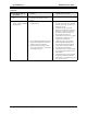
The following table lists the connections for a crossover cable.
Standard End Crossover End
Signal Name Wire Color Pin Pin Wire Color Signal Name
TD+ White/Orange 1
ÅÆ
3 White/Green RD+
TD- Orange 2
ÅÆ
6 Green RD-
RD+ White/Green 3
ÅÆ
1 White/Orange TD+
Not used Blue 4
ÅÆ
5BlueNot used
Not used White/Blue 5
ÅÆ
4 White/Blue Not used
RD- Green 6
ÅÆ
2 Orange TD-
Not used White/Brown 7
ÅÆ
8 White/Brown Not used
Not used Brown 8
ÅÆ
7BrownNot used