Model NCB/IM Network Combiner Module with Internal Modem Wide Area Router for LONW ORKS® Networks User Guide # S2-60419-310 68-10822-310
CTI Products, Inc. NCB/IM User Guide Standard Limited Hardware Warranty LIMITED WARRANTY. Equipment manufactured by CTI Products, Inc. is warranted to be free from defects in material and workmanship for a period of ONE (1) YEAR from date of shipment to original purchaser. Under this warranty, our obligation is limited to repairing or replacing any equipment proved to be defective by our inspection within one year of sale to the original purchaser.
CTI Products, Inc. NCB/IM User Guide This manual covers NCB units of Revision 300 or higher and NCB/Plug software revision 1.00 or higher. The NCB Unit Revision can be found on the rear of the unit following the letter “U”. The NCB/Plug software revision can be found on the Help/About screen of the program. If the revision of the product in hand is greater than that shown above, there may be additional features supported by the product that are not covered in this manual.
CTI Products, Inc. NCB/IM User Guide Radio Frequency Emissions and Immunity This equipment generates, uses, and can radiate radio frequency energy and, if not installed and used in accordance with the instruction manual, may cause harmful interference to radio communications. Operation of this equipment in a residential area is likely to cause harmful interference in which case the user will be required to correct the interference at his own expense.
CTI Products, Inc. NCB/IM User Guide TABLE OF CONTENTS QUICK-START GUIDE .............................................................................................................................................1 1. INTRODUCTION ...................................................................................................................................................3 WHAT IS AN NCB/IM UNIT? .........................................................................................................
CTI Products, Inc.
CTI Products, Inc. NCB/IM User Guide QUICK-START GUIDE This Quick Start Guide provides a concise series of steps to get a pair of the NCB modules “up and running” quickly so that initial operation may be confirmed. It is important that all LONW ORKS devices attached to the “NETWORK” connector of any one NCB module use the same network transceiver . See “LONW ORKS NETWORK TRANSCEIVERS” in section “1. INTRODUCTION”. In the following steps, identify the two units as “NCB Unit 1” and “NCB Unit 2”.
CTI Products, Inc.
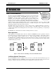
CTI Products, Inc. NCB/IM User Guide 1. INTRODUCTION WHAT IS AN NCB/IM UNIT? Read this section to learn the general function and capabilities of an NCB Router The Network Combiner NCB/IMTM Module is a wide-area router with an internal modem for LonWorks networks. The NCB/IM unit is used in pairs to connect LONW ORKS networks real-time, spanning distances from building-wide to worldwide.
CTI Products, Inc. NCB/IM User Guide NCB units are available with an option for LONW ORKS network transceiver type. The ordering code on the rear of the NCB lists the installed options. This ordering code is of the form: NCB/IM-Txxx-xx, where ‘T’ indicates the transceiver type. The following LONW ORKS network transceiver options are available: A = FTT-10A K = SMX RS485 B = TPT/XF-78 M = SMX PL22 C = TPT/XF-1250 X = None (SMX ready) Line Port The internal modem in the NCB/IM module uses proven V.
CTI Products, Inc. NCB/IM User Guide Router Function The router contained in each NCB module may be configured as a repeater, bridge, or configured router. The easiest configuration is as a repeater, where all messages which enter the NCB module (via any of the three data sources described above) are simply passed to the other two sources, regardless of the domain, subnet/node, or group destination address. A bridge only passes messages that match one of the two domain IDs configured on the router.
CTI Products, Inc.
CTI Products, Inc. NCB/IM User Guide CMD Button This button can be used to temporarily enable the Auto Answer function in Dial-up mode. This is useful if Auto Answer mode has been inadvertently disabled on a remote NCB. When this occurs, and a connection with this remote unit is broken, it will no longer automatically answer an incoming call. To re-enable Auto Answer mode, proceed as follows: Press and hold the “CMD” button on the remote NCB Press and release the “RESET” button on the remote NCB.
CTI Products, Inc. 1.
CTI Products, Inc. NCB/IM User Guide 2. SETUP AND OPERATION STEP 1. MOUNTING Follow the steps in this section to setup an NCB Router for the first time Non-slip rubber feet are included on all NCB modules to allow them to conveniently rest on any horizontal surface. Four 6-32 threaded holes are also available on the bottom of the module to allow bolting of the module in any convenient orientation. WARNING: Care should be taken to limit protrusion of the screw into the module to no more than 0.
CTI Products, Inc. NCB/IM User Guide Setting the Internal Modem Configuration (Switches 1, 2, 7, and 8) Will a Dial-Up line be used for this Network? ? If Manual or Perpetual Dial-up Mode is required, see “DIAL-UP CIRCUITS” following in this section. If using a leased telephone line, see “LEASED-LINE CIRCUITS” following in this section. Tutorial . . .
CTI Products, Inc. NCB/IM User Guide 2) OPTION A Switch 7 is used to set the transmit level from the modem and should be normally left in the UP position. If two NCB units are to be connected “back-to-back” in Leased-Line mode with only a short cable between the “LINE” connector on each unit (in lab test situations, for instance), Switch 7 must be set to the DOWN position in order for the two modems to connect properly.
CTI Products, Inc. NCB/IM User Guide Telephone Line Connection LINE The telephone circuit connection must be made using the “LINE” connector See APPENDIX C for connector type and pinout. Dial-Up A dial-up connection uses a 2-wire connection scheme to a standard telephone circuit. A standard telephone cord can be used.
CTI Products, Inc. NCB/IM User Guide utilizing a portion of the connection bandwidth. This utilization is dynamic and only consumes bandwidth when audio is detected into the “AUDIO” connector. NOTE: Data throughput across the modem channel is decreased by 7200 bits-per-second when audio input is detected at either handset.
CTI Products, Inc. NCB/IM User Guide Commissioning the NCB with LonMaker for Windows Commissioning each NCB in a network with LonMaker for Windows involves commissioning two different network devices, both contained in the single NCB enclosure: a standard LONWORKS router, and the control neuron. Since the standard LONW ORKS router portion of an NCB router interfaces a LONW ORKS channel to a Telephone (WAN) channel, it requires connection to two channels on the LonMaker drawing.
CTI Products, Inc. NCB/IM User Guide Specify a Location string and Description, if desired. “Ping Interval” can be set as desired, however should be set to “never” for remote NCB routers which are not connected full-time (for example, those connected via dial-up telephone lines). Click NEXT to continue. Specify desired advanced router properties. Router Type : Configured is recommended. Click FINISH to complete the “New Router Wizard”.
CTI Products, Inc. NCB/IM User Guide STEP 5. CONTROLLING THE WAN CONNECTION At this point, the “local” NCB (the one connected to the LonMaker for Windows NSI) has been configured and fully commissioned for use. This last step involves making a connection to the “remote” NCB via the Telephone (WAN) channel.
CTI Products, Inc. NCB/IM User Guide 3. NETWORK VARIABLE (NV) CONTROL TYPICAL NV BINDINGS This Section contains details of Network Variables and Bindings All commands sent to the NCB module are carried on the LonTalk network in the form of Network Variables bound to the Control Neuron processor inside the NCB module (connected to Side A of the internal router). This section details the Functional Blocks (objects) and the network variables of each.
CTI Products, Inc. NCB/IM User Guide The example in Figure 6 uses multiple Directory Objects with multiple Modem Controller Objects.
CTI Products, Inc. NCB/IM User Guide Network Variables Dial String (Input) C Language Syntax network input SNVT_str_asc nviDialStr1; network input SNVT_str_asc nviDialStr2; Usage A non-null string sent to this input network variable while the current modem connection state is TEL_NOTINUSE causes the modem to go off hook, wait for a dial tone, then perform a dialing sequence using the provided character string.
CTI Products, Inc. NCB/IM User Guide Connect Status (Output) C Language Syntax network output SNVT_telcom nvoCnctStat1; network output SNVT_telcom nvoCnctStat2; Usage This output network variable provides the current state of the modem connection process.
CTI Products, Inc. NCB/IM User Guide Request Dial String (Output) C Language Syntax network output SNVT_char_ascii nvoReqDialStr1; network output SNVT_char_ascii nvoReqDialStr2; Usage This output network variable is associated with Perpetual Dial-Up Mode (see Tutorial “Which Modem Mode Should Be Used” in section “2. SETUP AND OPERATION”) and is used when the Directory Object storing the telephone number (to be dialed) belongs to a node other than the call-originating NCB.
CTI Products, Inc. NCB/IM User Guide Phone Book Object Modem Controller Object nvoReqDialStr nviReqDialStr nvoDialStr nviDialStr Figure 7 Perpetual Dial-up Mode using NV Bindings Configuration Properties Will Configuration Properties be modified? If NO, and the NCB objects (functional blocks) will be used with factory default settings (Manual Dial-Up or Leased-Line modes, Auto Answer mode Enabled, Ring Mode disabled), skip to Directory Object, later in this section.
CTI Products, Inc. NCB/IM User Guide Dial Mode C Language Syntax Typedef struct UCPT_DialMode { unsigned char Mode; unsigned char Index; } network input config SCPTdialMode UCPT_DialMode1; network input config SCPTdialMode UCPT_DialMode2; Usage This input configuration network variable allows the modem dialing Mode (Manual or Perpetual) to be set, as well as the Directory entry Index number (0 through 15) that should be used when dialing in Perpetual mode.
CTI Products, Inc. Value Off On NCB/IM User Guide Auto Answer Mode Disabled Enabled Default State On (Enabled) TELEPHONE DIRECTORY OBJECT A Telephone Directory Object is used to store and retrieve arrays of ASCII strings that are characterized as telephone numbers (including characters used for control) used in dialing a data modem.
CTI Products, Inc. NCB/IM User Guide When Transmitted Transmitted upon receipt of a valid nviReqDialStr input, unless requested entry index is not supported or entry is blank (first character of entry is a NULL), in which case this variable is not transmitted.
CTI Products, Inc. 3.
CTI Products, Inc. NCB/IM User Guide 4. NCB/PLUG CONFIGURATION PLUG-IN LNS plug-ins are applications that can be started from within an LNS application (such as LonMaker for Windows) to perform a specialized task. The NCB/Plug configuration plug-in implements configuration and query commands for the NCB. The NCB/Plug plug-in and Network Variables can be used simultaneously.
CTI Products, Inc. NCB/IM User Guide ACCESSING NCB/PLUG a) Bring NCB/Plug to the desktop: b) Right click on the Control Neuron Functional Block to be configured (Modem, Directory, Globals). In the drop-down list, click “Configure”. The Plugin will appear as shown here. c) Alternatively, right click on the Control Neuron Processor device shape. In the dropdown list, click “Plug-Ins…”, and select NCB/Plug. Click OK to continue. The Plugin will appear as shown here.
CTI Products, Inc. NCB/IM User Guide Soft Reboot This is equivalent to pressing the “RESET” button on the NCB’s front panel. Modem Options Menu Item The Modem Options menu item provides access to the following functions for an NCB/IM: Auto Answer (Dial-Up only) This option allows enabling or disabling the Auto Answer function in Dial-up mode. A check next to the menu item indicates Auto Answer is currently enabled.
CTI Products, Inc. 4.
CTI Products, Inc. NCB/IM User Guide APPENDIX APPENDIX A. FACTORY DEFAULT CONFIGURATION Control Neuron Processor Restoring Factory Default Parameters Should the Control Neuron Processor communication parameters be overwritten incorrectly by a network management tool, they can be restored as follows: Press the “RESET” button on the front of the NCB unit After the “ERR” LED goes off, press the “RESET” button a second time. The Control Neuron communication parameters are now restored to factory defaults.
CTI Products, Inc. NCB/IM User Guide unconfigured mode before being installed into the system (this step is mandatory if redundant routers are to be configured). Refer to Technical Note TN025 for more information on configuration of the router with standard network management tools such as LonBuilder, LonMaker, LNS, and others. The SETRTR program requires a network interface to be connected to the personal computer.
CTI Products, Inc. NCB/IM User Guide APPENDIX B. MOUNTING OPTIONS Wall mount and EIA 19” rack mount kits are available as options for the NCB from CTI Products, Inc. The wall mount kit includes brackets to allow a single NCB module to be mounted to any flat surface. The rack mount kit includes an adaptor allowing up to three NCB modules to be mounted in a single rack unit height. Rack Mount Option The rack mount option allows up to three NCB modules to be mounted in a one rack unit height (1.
CTI Products, Inc. NCB/IM User Guide To attach a module to the rack adaptor, and then mount the rack adaptor into the rack, follow the steps below. WARNING Do not allow the PC board to slide out of the housing when the front panel is removed. If it does, DO NOT slide the PC board back into the housing from the front of the module. Doing so may damage the unit, causing the unit to malfunction when powered on. Doing so will void the unit’s warranty.
CTI Products, Inc. NCB/IM User Guide Wall Mount Option The wall mount option allows an NCB module to be mounted to any flat surface. The NCB module has four screw holes on the bottom. Simply attach the two mounting plates to the bottom of the module using the four flat-head screws provided with the wall mount kit. This assembly is then attached to the flat surface with userprovided fasteners. Figure 9 shows a dimensioned view of the wall mount installation.
CTI Products, Inc. NCB/IM User Guide APPENDIX C. CONNECTOR DETAILS DC IN Connector Connector type: 2.5 x 5.5 mm coaxial Mating Connector: Switchcraft 760 or equivalent Connector pinout: CTI Products, Inc. standard power supply wired with center pin positive, NCB module can accept either pin positive, polarity routing is provided internal.
CTI Products, Inc. NCB/IM User Guide 3 Pin Terminal Strip style: Mating Connector: Pin 1 2 3 NETWORK Weidmuller 128186 Function Network Network Shield (RS-485 only) 1 2 3 CA- 80085- 100 NETWORK SMX Transceiver units: SMX network connections are described in the documentation with the SMX transceiver. 2 1 Telco LINE Connector Connector type: Standard RJ11 telephone style, 6 position 4 contact.
CTI Products, Inc. NCB/IM User Guide AUDIO Connector Connection point for a telephone style handset or other audio device to make use of the simultaneous voice/data feature 1 Connector type: Standard RJ11 telephone type, 4 position 4 contact Pin 1 Function audio in 2 audio out 3 8 audio ground audio ground AUDIO 2 3 4 Notes Inactive during training, simultaneous voice audio in after training Line audio during training, simultaneous voice audio out after training Appendix C.
CTI Products, Inc. NCB/IM User Guide APPENDIX D. NCB VERSION COMPARISON Feature Version 3 Operation Auto-Answer Mode OPTION A Switch 1 determines the Auto(using Answer capability for dial-up operation. In OPTION A Switch 1) Dial-up Auto-Answer Enabled mode, an NCB can originate and answer a call. In Dial-up Auto-Answer Disabled mode, an NCB can only originate a call. Perpetual Dial-up Mode Perpetual Dial-up Mode will function when requirements for OPTION A Switch 1 is in either position.
CTI Products, Inc. NCB/IM User Guide APPENDIX E. TROUBLESHOOTING Table E1 If the PWR LED . . . REASON CORRECTIVE ACTION Is always illuminated. Normal operation indicating that NCB unit is receiving proper DC input power. Go to next Table. Flashes for 2 seconds. Normal operation when WINK command is being executed. Go to next Table. Flashes continuously. DC input to unit is below minimum required voltage. Check for proper voltage at “DC IN” connector (10-32VDC). Does not illuminate.
CTI Products, Inc. NCB/IM User Guide Does not illuminate on originating NCB when using a Dial-Up line and a connection is attempted. 1. DIAL command is not being sent correctly to originating NCB. 2. Defective modem. 1. Illuminates only briefly (less than 5 seconds) on originating NCB when using a Dial-Up line and a connection is required. Dial-up line is not operating to the telco switching equipment.
CTI Products, Inc. Does not illuminate within 45 seconds of illumination of “OH” LED on originating NCB when using a DialUp Line. NCB/IM User Guide 1. OPTION A Switch 1 is not set correctly. 1. 2. Incorrect dial string is being used by originating NCB. (While initiating a dial-up connection, and with a handset connected to the AUDIO connector of the originating NCB, the dial tone, followed by the dial sequence, followed by the repeating busy signal, can be heard.) 3.
CTI Products, Inc. NCB/IM User Guide Table E5 If the ACT LED (on local NCB) . . . REASON CORRECTIVE ACTION Occasionally blinks on, then off. Normal operation indicating a message packet has passed through the router module of the NCB. Go to next Table. Does not illluminate when “RSVC” button on remote NCB is pressed. 1. LONW ORKS Service Pin message from remote NCB is not reaching the local NCB. 1a. Verify that “ACT” and “ERR” LED’s on remote NCB flash once.
CTI Products, Inc. NCB/IM User Guide Table E6 Miscellaneous: REASON CORRECTIVE ACTION Cannot communicate with Control Neuron Processor of local NCB when using NODEUTIL. 1. In Bridge or Configured modes, router neurons and network interface are not in the same domain. 2. In Repeater mode, the network interface may be defective. 1. Cannot communicate with the Control Neuron Processor of local NCB when using NCBCON. 1.
CTI Products, Inc. NCB/IM User Guide APPENDIX F. SPECIFICATIONS NCB/IM Unit Power: 10 to 30 VDC, Negative Ground, Externally Current Limited 5 watts max. without SMX transceiver 10 watts max. with SMX power line transceiver North American and International Power Supplies available Size: 7.5" D x 5.6" W x 1.6" H Mounting: Desktop with integral non-slip feet Wall mount or 19" rack mount with optional adapters Temperature: 0-60C Humidity: 10-95% non-condensing Listings: UL1459, CSA C22.
CTI Products, Inc. NCB/IM User Guide APPENDIX G. MODEM NOTES Manual Dial-Up Mode (PSTN) Manual dial-up mode requires command information be sent to the originating NCB unit to cause it to dial the answering NCB unit. This command information is sent in the form of Network Variables bound to function blocks (objects) of the control Neuron processor inside the NCB module.
CTI Products, Inc. NCB/IM User Guide parameters and other housekeeping items, and concludes with the "CD" (carrier detect) LED illuminating. Within 2 seconds after this LED lights, data packets can flow across the modem connection and the simultaneous voice/data facility is enabled to the “AUDIO” connector. The elapsed time between training sequence start and end (carrier detect) is tracked by a timer inside each NCB unit.
CTI Products, Inc. NCB/IM User Guide 12. If the actions of step 9 or 10 do result in a periodic tone, proceed by connnecting the remaining pair from each NCB unit to each remaining telephone circuit pair at each site. Reset both NCB units (or wait for them to timeout and recycle, approximately 60 seconds) and they should complete the modem training process and turn on their “CD” LEDs within 30 seconds. See text in section “2. SETUP AND OPERATION”, “STEP 3.
CTI Products, Inc. NCB/IM User Guide INDEX A ACT LED ..................................................................6 AUDIO connector.......................................... 4, 13, 47 Auto Answer Mode ....................................... 7, 29, 46 B Back-to-back................................................ 11, 12, 48 Bridge ........................................................................5 Buffer Configuration ............................................... 31 C Call Cancel .............