
User Manual


CTI Products, Inc. NCB/IM User Guide
2. Setup and Operation 9
2. SETUP AND OPERATION
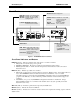
STEP 1. MOUNTING
Non-slip rubber feet are included on all NCB modules to allow them to
conveniently rest on any horizontal surface. Four 6-32 threaded holes are also
available on the bottom of the module to allow bolting of the module in any
convenient orientation. WARNING: Care should be taken to limit protrusion
of the screw into the module to no more than 0.125 inch from the module bottom surface!
Mounting kits are available as options to allow wall or rack (19” EIA) mounting
of the NCB module.
When wall or rack mounting the NCB, a suitable safety and protective earth
ground should be provided to the metal enclosure. The protective earth ground
provides a path to ground for electrostatic discharge (ESD) energy. This
connection is most conveniently made directly to the wall mount bracket or rack plate.
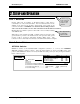
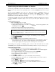
STEP 2. SWITCH SETUP
OPTION A Switches
OPTION A switches set the internal modem configuration (switches 1, 2, 7, and 8), and LONWORKS
addressing parameters (switches 5 and 6). Leave the unused switches (3 and 4) in the UP position. The
position of the OPTION A switches are read by the NCB at module power-up or after pressing the “RESET”
button on the front panel.
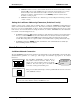
1
2
3
4
5
6
7
8
ON
1.
2.
3. Not Used
4. Not Used
5. Control Neuron Addressing Method....... Hardware Network Management Tool
6. Control Neuron Hardware Subnet/Node 255/2 255/1
7. Leased-Line Transmit Level .................. -10dBm (Normal) -16dBm (Back-to-back)
8. Leased-Line Wiring................................ 2-Wire 4-Wire
UP DOWN
Modem Mode
Modem Mode Switch: 1 2
Dial-up: Auto Answer Enabled UP UP
Dial-up: Auto Answer Disabled DN UP
Leased-Line: Answer UP DN
Leased-Line: Originate DN DN
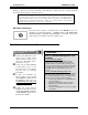
See Appendix B
for Mounting
Option details.
Follow the steps
in this section to
setup an NCB
Router for the
first time