
Assembly Owner's manual


CTI Products, Inc. OTAL Driver Assembly User Guide
REMOTE PTT CIB CONNECTIONS
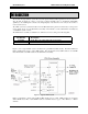
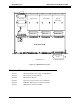
Remote PTT signals are connected to J1 on a remote CIB. (See Figure 1.) PTT inputs are not required if COR
Only OTAL Logic is used.
Remote PTT signals shall be either:
Isolated Form A Relay Contacts (or opto-isolated relay outputs)
closed when PTT signal is present.
Logic Outputs - Negative Ground, Active Low when PTT is active.
They must be capable of:
Up to +20 VDC Open Circuit
Sinking a minimum of 30 mA when active
Maximum of 0.2 V when active
Signals must not drive other equipment.
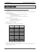
The Remote PTT signals appear on the following pins of J1 of the remote PTT CIB module as follows:
Remote PTT CIB J1 Wire Color CIB Function OTAL System Function
1 Blu/Wht Ground Ground-Common
22 Org/Vio Rx 1 PTT 1B input
47 Vio/Org Rx 2 PTT 2B input
16 Blu/Yel Rx 3 PTT 3B input
41 Yel/Blu Rx 4 PTT 4B input
10 Slt/Red Rx 5 PTT 5B input
35 Red/Slt Rx 6 PTT 6B input
4 Brn/Wht Rx 7 PTT 7B input
29 Wht/Brn Rx 8 PTT 8B input
The “B” suffix on the PTT signals indicates the Remote PTT.
REMOTE COR CIB CONNECTIONS
The Remote COR signals are connected to J1 on a remote CIB. (See Figure 1.)
Remote COR signals shall be either:
Isolated Form A Relay Contacts (or opto-isolated relay outputs)
closed when a carrier is detected.
Logic Outputs - Negative Ground, Active Low when a carrier is active.
They must be capable of:
Up to +20 VDC Open Circuit
Sinking a minimum of 30 mA when active
Maximum of 0.2 V when active
Signals must not drive other equipment.
Field Connections 10