
Assembly Owner's manual


CTI Products, Inc. OTAL Driver Assembly User Guide
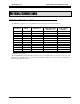
The Remote COR signals appear on the following pins of J1 of the remote COR CIB module as follows:
Remote COR CIB J1 Wire Color CIB Function OTAL System Function
1 Blu/Wht Ground Ground-Common
22 Org/Vio Rx 1 COR 1 input
47 Vio/Org Rx 2 COR 2 input
16 Blu/Yel Rx 3 COR 3 input
41 Yel/Blu Rx 4 COR 4 input
10 Slt/Red Rx 5 COR 5 input
35 Red/Slt Rx 6 COR 6 input
4 Brn/Wht Rx 7 COR 7 input
29 Wht/Brn Rx 8 COR 8 input
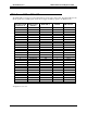
OTAL OUTPUTS
The OTAL outputs are opto-isolated solid state relays. They are active in the closed position. These outputs
appear on the last 8 pairs of J1 of the OTAL Driver Assembly as follows:
OTAL Driver Assembly J1 Wire Color Signal
43
Yel/Grn OTAL Ry 1+
18
Grn/Yel OTAL Ry 1-
44
Yel/Brn OTAL Ry 2+
19
Brn/Yel OTAL Ry 2-
45
Yel/Slt OTAL Ry 3+
20
Slt/Yel OTAL Ry 3-
46
Vio/Blu OTAL Ry 4+
21
Blu/Vio OTAL Ry 4-
47
Vio/Org OTAL Ry 5+
22
Org/Vio OTAL Ry 5-
48
Vio/Grn OTAL Ry 6+
23
Grn/Vio OTAL Ry 6-
49
Vio/Brn OTAL Ry 7+
24
Brn/Vio OTAL Ry 7-
50
Vio/Slt OTAL Ry 8+
25
Slt/Vio OTAL Ry 8-
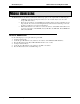
The solid-state relay outputs listed above are polarity-sensitive, and are current-limited to 0.5A. Typical lamp
connections are shown below.
Figure 5 – Typical Lamp Connections
Field Connections 11