
Assembly Owner's manual


CTI Products, Inc. OTAL Driver Assembly User Guide
INTERNAL CONNECTIONS
PTT IIB TO OTAL DRIVER PCB
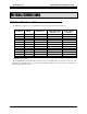
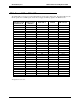
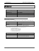
The PTT IIB is connected to J2 on the OTAL Driver board through a ribbon cable as follows:
PTT IIB J1 IIB I/O IIB Function
OTAL Driver PCB
Connector J2
OTAL System
Function
1
Gnd Ground 1 Ground
4
I Link Fail Enable 7 Ground
29
I Link Fail Invert 8 Ground
30
O Fail 8 / Link Fail 10 LinkUp1
19
O Rx 1 37 PTT 1B
44
O Rx 2 38 PTT 2B
12
O Rx 3 23 PTT 3B
37
O Rx 4 24 PTT 4B
6
O Rx 5 11 PTT 5B
31
O Rx 6 12 PTT 6B
18
O Rx 7 35 PTT 7B
26
O Rx 8 2 PTT 8B
All signals are active low.
The Link Fail Enable and Link Fail Invert signals are inputs to the IIB. They are read-only at power-up of the
IIB. Therefore, the IIB must be connected to the OTAL Driver PCB before it is powered up. Otherwise, the
Link UP signal will not be active.
Internal Connections 13