
Assembly Owner's manual


CTI Products, Inc. OTAL Driver Assembly User Guide
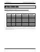
COR IIB TO OTAL DRIVER PCB
The COR IIB is connected to J3 on the OTAL Driver board through a ribbon cable as follows:
COR IIB J1 IIB I/O IIB Function
OTAL Driver PCB
Connector J3
OTAL System
Function
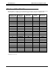
1
Gnd Ground 1 Ground
4
I Link Fail Enable 7 Ground
29
I Link Fail Invert 8 Ground
30
O Fail 8 / Link Fail 10 LinkUp2
19
O Rx 1 37 COR 1
44
O Rx 2 38 COR 2
12
O Rx 3 23 COR 3
37
O Rx 4 24 COR 4
6
O Rx 5 11 COR 5
31
O Rx 6 12 COR 6
18
O Rx 7 35 COR 7
26
O Rx 8 2 COR 8
All signals are active low.
The Link Fail Enable and Link Fail Invert signals are inputs to the IIB. They are read only at power-up of the
IIB. Therefore, the IIB must be connected to the Otal Driver PCB before it is powered up. Otherwise, the Link
UP signal will not be active.
Internal Connections 14