
Assembly Owner's manual


CTI Products, Inc. OTAL Driver Assembly User Guide
SAMPLE SCREEN
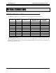
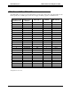
A sample screen (including Remote PTT inputs and COR+PTT OTAL Logic) is shown below:
OTAL Screen 1
Local PTTs Remote PTTs
CORs OTAL Logic
OTAL 1 AC OK CIB Link OK CIB Link OK OTAL DC OK
Chan 1 Chan 1 Chan 1 Chan 1
Chan 2 PTT Chan 2 Chan 2 COR Chan 2 OTAL
Chan 3 Chan 3 Chan 3 Chan 3
Chan 4 Chan 4 PTT Chan 4 COR Chan 4 OTAL
Chan 5 Chan 5 Chan 5 Chan 5
Chan 6 Chan 6 Chan 6 COR Chan 6
Chan 7 Chan 7 Chan 7 COR Chan 7
Chan 8 Chan 8 Chan 8 COR Chan 8
OTAL 2 AC OK CIB Link OK CIB Link OK OTAL DC ON
Chan 9 Chan 9 Chan 9 Chan 9
Chan 10 PTT Chan 10 Chan 10 Chan 10 Fail
Chan 11 Chan 11 Chan 11 Chan 11
Chan 12 Chan 12 PTT Chan 12 Chan 12 Fail
Chan 13 Chan 13 Chan 13 Chan 13
Chan 14 Chan 14 Chan 14 Chan 14
Chan 15 Chan 15 Chan 15 Chan 15
Chan 16 Chan 16 Chan 16 Chan 16
• The channel names can be customized in the MCN Config program.
• The status of the power, along with the status of the CIB Links are shown above each group of 8 channels.
• Channel 2 shows a channel that is normally keyed using the Main PTT. The COR signal is active and the
OTAL Driver Assembly is generating an OTAL signal.
• Channel 4 shows a channel with normal keying using the Remote PTT.
• Channels 6-8 show receive traffic. Since there are no PTT signals (and the system is using COR + PTT OTAL
Logic), the OTAL lights are off.
• Channel 10 shows an abnormal situation. The Main PTT signal is active, but there is no received signal and
therefore, no OTAL light. This could be caused by any number of problems, including a bad transmitter, bad
phone line, or a bad receiver.
• Channel 12 shows a similar abnormal situation, but with an attempted transmission using the Remote PTT.
PC Display 20