
Assembly Owner's manual


CTI Products, Inc. OTAL Driver Assembly User Guide
FIELD CONNECTIONS
LOCAL PTT CONNECTIONS
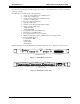
Local PTT signals are connected to J1 of the OTAL Driver PCB. (PTT inputs are not required if COR Only
OTAL Logic is used.)
Local PTT signals shall be either:
Isolated Form A Relay Contacts (or opto-isolated relay outputs)
closed when PTT signal is present.
Logic Outputs - Negative Ground, Active Low when PTT is active.
They must be capable of:
Up to +20 VDC Open Circuit
Sinking a minimum of 30 mA when active
Maximum of 0.2 V when active
Signals must not drive other equipment.
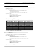
The Local PTT signals appear on the first 8 pairs of J1 as follows:
OTAL J1 Wire Color Signal
1 Blu/Wht PTT 1A
26 Wht/Blu Gnd 1A
2 Org/Wht PTT 2A
27 Wht/Org Gnd 2A
3 Grn/Wht PTT 3A
28 Wht/Grn Gnd 3A
4 Brn/Wht PTT 4A
29 Wht/Brn Gnd 4A
5 Slt/Wht PTT 5A
30 Wht/Slt Gnd 5A
6 Blu/Red PTT 6A
31 Red/Blu Gnd 6A
7 Org/Red PTT 7A
32 Red/Org Gnd 7A
8 Grn/Red PTT 8A
33 Red/Grn Gnd 8A
(The “A” suffix on the PTT signals indicates the Local PTT.)
The ground signals are tied together on the OTAL Driver board. It is preferred that the PTT signals be wired to
J1 as pairs, with separate grounds.
Field Connections 9