OTAL Terminal Board And Lamp Assembly User Guide # S2-61145-100 68-12002-100
CTI Products, Inc. OTAL Terminal Board User Guide Standard Limited Hardware Warranty LIMITED WARRANTY. Equipment manufactured by CTI Products, Inc. is warranted to be free from defects in material and workmanship for a period of ONE (1) YEAR from date of shipment to original purchaser. Under this warranty, our obligation is limited to repairing or replacing any equipment proved to be defective by our inspection within one year of sale to the original purchaser.
CTI Products, Inc. OTAL Terminal Board User Guide TABLE OF CONTENTS Terminal Board........................................................................................................................................... 5 INTRODUCTION ...........................................................................................................................................................5 INSTALLATION .......................................................................................................
CTI Products, Inc.
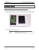
CTI Products, Inc. OTAL Terminal Board User Guide TERMINAL BOARD INTRODUCTION The OTAL Terminal Board is an accessory to the On The Air Light (OTAL) Driver Assembly. It allows field connection of an On The Air Light, a Power Supply, and the relay contacts from the OTAL Driver Assembly.
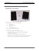
CTI Products, Inc. OTAL Terminal Board User Guide INSTALLATION Mounting Plate & Cover Installation Figure 2 OTAL TB Mounting Plate & Cover Kit The Mounting Plate & Cover Kit includes the following items: (1) Mounting Plate (2) Hex Threaded Standoffs (1) Plastic Cover (2) 6-32 x ¼" Philips Head screws If you ordered multiple kits, they will be bulk-packed. To install the OTAL Terminal Board, Mounting Plate & Cover Kit: 1.
CTI Products, Inc.
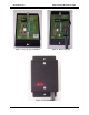
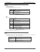
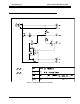
CTI Products, Inc. OTAL Terminal Board User Guide WIRING J1 Power Connector Power can be applied through the DC Power Connector J1: Pin Center Barrel Function + Supply In (typically 24VDC) (Paralleled with TB1-1) - Supply In (Typically Ground) (Paralleled with TB1-1) Table 1 – J1 Power Connector TB1 Terminal Board TB1 is for the field wiring.
CTI Products, Inc. OTAL Terminal Board User Guide SPECIFICATIONS Inputs & Outputs Power In: 12 to 24 VDC (nominal) 1A maximum DC Connector: 5.5 mm barrel x 2.5 mm center pin, center positive Lamp Drive Out 12 to 24 VDC (nominal – depending on power input) at 1A maximum Control In: Dry Closure or Open Collector/Drain Voltage level dependent upon power supply to board (12-24 VDC Nominal) 10 mA maximum Physical Size: Terminal Board 4.8" x 2.8" x 1.
CTI Products, Inc.
CTI Products, Inc.
CTI Products, Inc.