MCN Monitoring and Control Network Comparator Display System Remote Comparator Display Software Installation and Operator Manual S2-60428-210 68-10856-210
CTI Products, Inc. 1211 W. Sharon Rd. Cincinnati, OH 45240 If you have questions about the Remote Comparator Display system, call us at: (513) 595-5900. (8:30 to 5:00 Eastern) Information contained in this document is subject to change without notice and does not represent a commitment on the part of CTI Products, Inc.
CTI Products Inc. License Agreement Monitoring and Control Network Remote Comparator Display Software Single-User Products This is a legal agreement between you, the end user, and CTI Products Inc. By opening this sealed disk package, you are agreeing to be bound by the terms of this agreement. CTI Products Inc. Software License 1. GRANT OF LICENSE. Once you have paid the required Single-User License Fee, CTI Products Inc.
MCN Remote Comparator Display CTI Products, Inc. 1. INTRODUCTION, AND OVERVIEW.......................................................................................................... 1 1.1 NETWORK INTERFACE SUPPORT ........................................................................................................ 2 1.2 SYSTEM HARDWARE REQUIREMENTS ............................................................................................................... 3 1.3 REFERENCE DOCUMENTS ................
MCN Remote Comparator Display CTI Products, Inc. 6.5.4 ASSIGNING A UNIT ADDRESS TO THE HIB OR PCLTA ............................................................................ 28 6.5.5 ADDING CHANNEL TITLES TO THE DISPLAY SCREEN .............................................................................. 29 6.5.6 PLACING RECEIVERS ON THE SCREEN ..................................................................................................... 31 6.5.
MCN Remote Comparator Display CTI Products, Inc. 10.1.2 THE MODEM.INI FILE......................................................................................................................... 98 10.1.3 LEASED LINE MODEMS ....................................................................................................................... 101 10.1.4 TESTING LOCAL BACK TO BACK MODEMS ......................................................................................... 102 10.2 MODEM PROGRAMMING .....
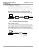
MCN Remote Comparator Display CTI Products, Inc. Introduction & Overview 1. Introduction, and Overview A basic MCN Remote Comparator Display system is shown in Figure 1. The MCN Remote Comparator Display system consists of the Host Computer Interface (HIB) Module and any MCN Comparator I/O Module (such as an AIB or CIB). The PC runs the MCN Remote Comparator Display software (MCN RCD) described in this manual. This manual covers the installation and operation of the software.
MCN Remote Comparator Display CTI Products, Inc. Introduction & Overview General Purpose I/O Devices require General Purpose Monitoring and Control Function The MCNRCD software can also monitor general purpose I/O devices connected to CIB or IOB modules.
MCN Remote Comparator Display CTI Products, Inc. Introduction & Overview Early HIB modules (‘xxx’ is less than 200): • Support only local operation with MCNRCD. Skip all modem references in this manual. • External module that connects to one of the PC’s COM ports. • Requires device driver LDVSLTA.SYS to be loaded by your PC’s CONFIG.SYS file (see section 5). All other HIB modules (‘xxx’ is 200 or greater): • Support both local and remote operation with MCNRCD.
MCN Remote Comparator Display CTI Products, Inc. Introduction & Overview able to operate the MCNRCD software at the highest baud rate (38400 bps). You may have to run at either 14400 bps or 9600 bps. If your COM port uses a 16450 or 8250 type UART, and you are running at 38400 bps, and you get the HIB communication error screen (see section 7.2.2.
MCN Remote Comparator Display CTI Products, Inc. Theory of Operation 2. Theory of Operation This section describes the operation of the MCN Remote Comparator Display software in an MCN comparator display system. 2.1 Comparator Status The Comparator I/O Module (such as an AIB or CIB) accepts the VOTE, RECEIVE, DISABLE, and FAIL receiver status indicators from the comparator. It sends status messages to the HIB or PCLTA. The HIB or PCLTA passes the messages over the PCs serial port to the MCNRCD software.
MCN Remote Comparator Display CTI Products, Inc. Quick Start 3. Quick Start We recommend that you first set up the entire system, including PC, modems, HIB or PCLTA, Comparator I/O Device, and any other equipment in the same room to verify system cabling and operation. After the system is up and running, install the individual items at their proper locations. To install the system, do the following steps in order: 1. Read section 4 of this manual. 2.
MCN Remote Comparator Display CTI Products, Inc. MCNRCD & MCNCFG Basics 4. MCNRCD & MCNCFG Basics 4.1 Using Menu Commands To access the menu commands, click the menu item with the left mouse button. To use the keyboard to access menu commands, press the A key and the highlighted letter for the menu command. For example, to access the File menu, click the mouse cursor on the File option on the menu bar or press Af key combination on the keyboard. Some menu commands may not be valid at certain times.
MCN Remote Comparator Display CTI Products, Inc. MCNRCD & MCNCFG Basics 4.2.2 MCN Screen Files .MSF Each screen that you want to display requires a MCN Screen File (.MSF). The MCN Screen Files include the following: • Module address of the HIB • Which MCN Groups to display (up to 4) • Screen Name • Channel Title information • Receiver Placement on the screen You can make multiple MCN Screen Files that all use the same GCF configuration files if all your receivers won’t fit on one screen.
MCN Remote Comparator Display CTI Products, Inc. MCNRCD & MCNCFG Basics 4.2.7 MCN Statistics Log File (MCNSTAT.LOG) This file contains the statistics log entries in an ASCII text form. See section 7.6.2 for more information about statistics logging. 4.2.8 MCN Text Configuration File (MCNRCD.CFG) This file holds the receiver status text messages that are displayed for the VOTE, RECEIVE, DISABLE and FAIL states. This file can be changed so that you can customize the displayed status messages.
MCN Remote Comparator Display CTI Products, Inc. Installation 5. Installation 5.1 Installing the Remote Comparator Display Software To Install the Remote Comparator Display Software 1. C:> MD CTI E 2. C:> CD CTI E 3. Insert CTI MCN Remote Comparator Display disk in A: 4. C:\CTI> COPY A:*.* E 5. Modify your CONFIG.SYS file as shown in section 5.2 of this manual. 6. Modify your AUTOEXEC.BAT file as shown in section 5.4 of this manual. 7.
MCN Remote Comparator Display CTI Products, Inc. Installation 5.4 Modifying the AUTOEXEC.BAT File If you use a MOUSE.COM mouse driver, make sure its entry is in AUTOEXEC.BAT. If you use a serial mouse, be sure its COM port does not conflict with the serial port for the HIB. Be sure to re-boot the computer after any changes. 5.5 Network Interface Installation & Cabling The physical installation of the HIB module is covered in the HIB’s hardware reference manual, reference 2.
MCN Remote Comparator Display CTI Products, Inc. Configuring a System Using MCNCFG 6. Configuring a System -- Using MCNCFG A basic remote comparator display system consists of a PC connected to a HIB or PCLTA and one or more Comparator I/O Modules (see Figure 1). An MCN Group Configuration file (.GCF extension) contains all of the receiver information for MCN Comparator I/O Modules addressed into a single MCN Group. MCN Screen Files (.
MCN Remote Comparator Display CTI Products, Inc. Configuring a System Using MCNCFG 2. Build a MCN Screen File (SCF): a) Use the Files New Screen menu command to open a new MCN Screen File. b) The Active Group Files dialog box will appear. Press E to pop up a list of GCF files. Select the GCF file(s) that you want to display on the screen. Tab to and press E. c) The Select Active Group File dialog box will be displayed. Select the Group Configuration File you wish to work with first.
MCN Remote Comparator Display CTI Products, Inc. Configuring a System Using MCNCFG To get a complete list of the File Menu commands, press the f key. This displays the pull-down File Menu as in Figure 3. Each of the pull-down menus has a short cut activation key. This key is the intensified character in the menu name. Pressing the H key + the intensified letter of the menu will activate menu. Figure 3 - MCNCFG File Menu With the mouse, each menu can be activated by clicking on the menu name.
MCN Remote Comparator Display CTI Products, Inc. Configuring a System Using MCNCFG If you were working on a module set or screen file and had not yet saved it when you selected the Files New Group Configuration menu command, the program will give you a chance to save it. Figure 4 - New Group Configuration Screen 6.4.1 Group Configuration Screen Description The Group Configuration screen has entries for a total of 128 receiver (8 receivers x 16 different modules).
MCN Remote Comparator Display CTI Products, Inc. Configuring a System Using MCNCFG 6.4.2 Defining a Group Number Using the Edit Group Number menu command, you can define the MCN Group for the Comparator I/O Modules being monitored. Figure 5 shows the pull-down Edit Menu during Group Configuration. Figure 5 - Group Configuration Edit List Figure 6 shows the dialog box that appears when the Group Number menu command is executed. Enter a new Group number in the range shown on the screen.
MCN Remote Comparator Display CTI Products, Inc. Configuring a System Using MCNCFG Figure 6 - Group Number Editing 6.4.3 Entering Receiver Names Enter a descriptive name for each receiver controlled by the Comparator I/O Modules. This will usually be a site name. The receiver name will be displayed on the PC screen to identify the receiver. It is a 13-character alphanumeric field. Typical entries may be "Comm Center", "North Union", "East Bend" and the like.
MCN Remote Comparator Display CTI Products, Inc. Configuring a System Using MCNCFG 6.4.4 Entering Channel Name/Note Field The Channel Name/Note field is a 39 character alphanumeric field used to identify the channel for each receiver. When you build your Group Configuration Files, enter a channel name or number for each receiver so you can identify the channel for each receiver at a common site.
MCN Remote Comparator Display CTI Products, Inc. Configuring a System Using MCNCFG Figure 7 - Module Configuration Editing When moving around this screen without a mouse, you must use the T key to moved between selections. To exit the screen, press the T key until the cursor is on the OK or CANCEL button and then press E. 6.4.5.1.1 Defining the Module’s Status Text Category From this screen you can program in the status text category that you want used for the Comparator I/O Module.
MCN Remote Comparator Display CTI Products, Inc. Configuring a System Using MCNCFG 6.4.6 Group Configuration File Editing Keys The table below lists the editing key commands available to edit the Group Configuration File. • RIGHT ARROW R The RIGHT ARROW R key moves the cursor non-destructively one character position to the right in the field. • When the cursor reaches the end of the field, the RIGHT ARROW R key moves the cursor to the beginning of the next field.
MCN Remote Comparator Display CTI Products, Inc. • • • Configuring a System Using MCNCFG CTRL+ HOME IF you press CTRL+HOME at the same time the cursor is moved to the beginning (receiver #1) of the receiver list. CTRL+END CTRL+END moves the text cursor to the last receiver (receiver #152) of the receiver list. CTRL+D (DITTO) CTRL+D copies the text (either a receiver name or a channel description) from the line above to the current line.
MCN Remote Comparator Display CTI Products, Inc. Configuring a System Using MCNCFG 6.4.7 Inserting and Deleting Receivers If you make a mistake by skipping or duplicating a receiver when entering your receivers, you can insert or delete a receiver at the current position of the database. Use the following editing keys to Insert or Delete receivers: SHIFT+INS This inserts a blank entry at the current receiver number location and moves all of the following receivers down one row.
MCN Remote Comparator Display CTI Products, Inc. Configuring a System Using MCNCFG 6.4.
MCN Remote Comparator Display CTI Products, Inc. Configuring a System Using MCNCFG Figure 10 - Example Group Configuration Figure 11 - Example Group Configuration (continued) Figure 10 and Figure 11 show an example of the receiver names entered for this system. Notice that the Grp field, entered in step 3 above, of the receiver names is 00.
MCN Remote Comparator Display CTI Products, Inc. Configuring a System Using MCNCFG Now you have a file named SYSTEM1.GCF that defines all of the receivers for this system. Section 6.5.1 describes how this file will be used to create a MCN Screen File. 6.5 Building a Display Screen for your system Now that you have your Group Configuration File built, it’s time to start building a display screen. A typical screen is shown below. A description of the different fields will follow.
MCN Remote Comparator Display CTI Products, Inc. Configuring a System Using MCNCFG receiver number, including the MCN Group and Module number of the Comparator I/O Module for the receiver and receiver Desc./Notes. Tip: It is a good idea to move the cursor over each receiver on the screen and use the Channel Description field at the bottom of the screen to verify the proper channel assignments after you are finished building your screen. 6.5.
MCN Remote Comparator Display CTI Products, Inc. Configuring a System Using MCNCFG 6.5.2 Specify Group Configurations Dialog Box When you build a screen, you must select the Group Configuration File(s) that contain the receivers you want to monitor and control. Up to four different MCN Groups can be monitored and controlled in a single MCN Screen File. To Select Group Configuration Files: 1. The cursor will start in Group File 1. 2. Press the E key or left-click the mouse in the Group File 1 box.
MCN Remote Comparator Display CTI Products, Inc. Configuring a System Using MCNCFG 6.5.3 Selecting One Group to Work With -- Set Active Group Dialog Box When you place receivers on a display screen, you can work with receivers from only one Group file at a time. To select Group file 1, press E to select that .GCF file. Select one of the other Group files to work with by using the Z or Y keys. Press the T key to get to the OK button and then press E. You can also select a Group file with the mouse.
MCN Remote Comparator Display CTI Products, Inc. Configuring a System Using MCNCFG using the Edit HIB Address command. Figure 16 shows the dialog box that appears. Figure 16 - HIB Address Entry Dialog Box To enter a new address for the HIB or PCLTA, do the following: 1. For the Group number, enter a number between 00 and FE (hex). The default Group number is 80 (hex). 2. T over to the Module number field and enter a number between 0 and F (hex). 3.
MCN Remote Comparator Display CTI Products, Inc. Configuring a System Using MCNCFG Tip: As you build your display, you can add Channel Titles and place Receivers in whatever order you want. (You don’t have to add all the Channel Titles first.) It is usually easier to enter a Channel Title and place the receivers for that channel. You can then determine where to place the Channel Title and Receivers for the next channel.
MCN Remote Comparator Display CTI Products, Inc. Configuring a System Using MCNCFG 6.5.6 Placing Receivers on the Screen Once you have either created a new Screen File or opened an existing one, you are ready to determine where the receivers will appear on the screen. The MCNCFG Program is now in the Place Receivers mode. Figure 17 - Placing Receivers on a Display Screen To Place a Receiver on the Screen With the Keyboard... 1.
MCN Remote Comparator Display CTI Products, Inc. Configuring a System Using MCNCFG With the Mouse... 1. Select the position where you wish to place a receiver by clicking the left mouse button on that area of the screen. The Keyboard cursor is moved to the area you selected and the receiver list box appears. 2. Select a receiver to be displayed in that position. To select a receiver use the mouse to double click on the desired receiver name.
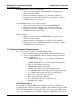
MCN Remote Comparator Display CTI Products, Inc. Configuring a System Using MCNCFG Figure 18 - Entering a Screen Name 6.5.9 Entering the HIB Telephone Number / Modem Dialing String If you are using the MCNRCD and HIB with dial-up modems, you must enter a modem dialing string (the phone number for the HIB location) into the screen file. To program the dialing string for this screen: 1 While the screen file is loaded press H, e, d or pick the Edit Dialing String menu command with the mouse.
MCN Remote Comparator Display CTI Products, Inc. Configuring a System Using MCNCFG Figure 19 - Entering the HIB Dialing String The dialing string consists of: Description Typical Entry 1. Modem Attention Code ATDT 2. PBX Access Codes & Wait (if needed) 9W 3. HIB Modem Telephone Number 555-1234 The above example would be entered as: "ATDT9W555-1234" (Don’t enter the quotes.) For more information on your modems dialing commands consult your modems documentation and section 10 for more details.
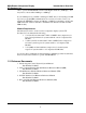
MCN Remote Comparator Display CTI Products, Inc. Configuring a System Using MCNCFG 6.5.10 Saving the MCN Screen File When you are finished building your screen, you must save the MCN Screen File. Tip: Before you save the file, it is a good idea to move the cursor over each receiver on the screen and use the Channel Description field at the bottom of the screen to verify the proper channel assignments. Use the Files Save menu command to save your MCN Screen File.
MCN Remote Comparator Display CTI Products, Inc. Configuring a System Using MCNCFG 10. If your MCN HIB module has a unit number where ‘xxx’ is less than 200 or if you are using a PCLTA card, you must execute the Edit HIB Address command to specify the MCN address of the HIB module that will be connected to this PC. For the Group number box, enter 80. Press the T key to move the cursor to the Module entry box. For the Module number box, enter 0.
MCN Remote Comparator Display CTI Products, Inc. Configuring a System Using MCNCFG 6.5.12 Exiting the Configuration Program When you are finished building the Group and MCN Screen Files, use the Files Exit menu command to quit the program. If you try to exit and have not yet saved your work, a Save Changes warning dialog box will be displayed. 6.6 Additional MCNCFG Menu Commands and Dialog Boxes The above tutorial took you through the creation of new Group and MCN Screen Files.
MCN Remote Comparator Display CTI Products, Inc. Configuring a System Using MCNCFG 4. The program will save the file with the proper extension (GCF for Group Configuration Files and MSF for MCN Screen Files). 5. Note: The original file will not be deleted or modified. 6.6.4 MCNCFG “File Already Exists” Warning If you do a File Save As menu command and you specify a file name that is already used, the MCNCFG program will display a File Already Exists warning dialog box.
MCN Remote Comparator Display CTI Products, Inc. Running the MCN Comparator Display (MCNRCD) Program 7. Running the MCN Comparator Display (MCNRCD) Program This section shows you how to operate the MCN Remote Comparator Display (MCNRCD.exe) program. • • • • • • • Starting the MCNRCD Program -- Quick Start Loading a Screen File (*.
MCN Remote Comparator Display CTI Products, Inc. Running the MCN Comparator Display (MCNRCD) Program Figure 21 - MCNRCD File Load Screen Quick Start Hint: To initially test your system, load the DEFAULT.MSF screen file before you build your custom Group Configuration Files and MCN Screen Files. This is a pre-built MCN Screen File that is shipped with the MCNRCD software. It is pre-configured for Comparator I/O Modules addressed to both Group 00 and Group 01.
MCN Remote Comparator Display CTI Products, Inc. Running the MCN Comparator Display (MCNRCD) Program 7.2.1 Modem Dialing If you are using a MCN RCD system with dial-up modems, the MCNRCD program will go through a dialing sequence to connect to the remote HIB. The program reads the dialing string from the MCN Screen File (*.MSF), or the MCNRCD command line, and proceeds to make the connection.
MCN Remote Comparator Display CTI Products, Inc. Running the MCN Comparator Display (MCNRCD) Program 7.2.2 System Initialization When the screen file is loaded, an MCN Initialization message box will appear on the screen. This message box will show the progress of the HIB initialization, as shown in Figure 23. When this message box appears, MCNRCD attempts to communicate with and initialize the HIB or PCLTA.
MCN Remote Comparator Display CTI Products, Inc. Running the MCN Comparator Display (MCNRCD) Program communications with each module individually to find out which modules are actually connected to the MCN network and operating. If all of the configured Comparator I/O Modules are connected to the MCN network and are powered, this module configuration will take only a second or two.
MCN Remote Comparator Display CTI Products, Inc. 7.2.2.1 Running the MCN Comparator Display (MCNRCD) Program HIB Initialization Failures During the HIB initialization sequence, see Figure 23, if MCNRCD is not able to establish communications with the HIB, MCNRCD will time out and display the error message shown in Figure 25. This error message will also be displayed if, during system operation, MCNRCD is no longer able to communicate with the HIB.
MCN Remote Comparator Display CTI Products, Inc. Running the MCN Comparator Display (MCNRCD) Program 7.3 MCNRCD Information Screen An Information option is available in the File menu that gives various information about the MCNRCD system. Figure 26 shows the information available when a screen file is loaded. Figure 26 - MCNRCD Information Box The software version number is the version number for MCNRCD. The HIB address is the MCN module address for the HIB. Module type is the HIB’s model number.
MCN Remote Comparator Display CTI Products, Inc. Running the MCN Comparator Display (MCNRCD) Program 7.
MCN Remote Comparator Display CTI Products, Inc. Running the MCN Comparator Display (MCNRCD) Program The Receiver Indicators display the status of the receivers.
MCN Remote Comparator Display CTI Products, Inc. Running the MCN Comparator Display (MCNRCD) Program To Re-Enable a receiver: To re-enable a site, place the mouse cursor over the previously disabled receiver and click the right mouse button. Quick Start Tech Note: Test the FORCE VOTE and DISABLE functions for each receiver on the screen and verify the operation at the comparator.
MCN Remote Comparator Display CTI Products, Inc. Running the MCN Comparator Display (MCNRCD) Program The first is Error logging, which is used to log only failure information. This information can be logged to the screen, the disk or both. The Show Errors On Screen [ ] box enables the program’s status line to display the error message received. The second type of logging is Statistics logging, which is used to log all changes from all Comparator I/O modules.
MCN Remote Comparator Display CTI Products, Inc. Running the MCN Comparator Display (MCNRCD) Program 7.6.1 Error Logging MCNRCD provides the capability to continuously monitor your comparator/voting receiver system. MCNRCD optionally reports detected errors to the display screen and/or a log file. Maintenance and supervisory personnel use these reports to track down intermittent system problems.
MCN Remote Comparator Display CTI Products, Inc. Running the MCN Comparator Display (MCNRCD) Program Whenever the MCNERR.LOG file is 100% full, it will automatically be reduced to 50% of its selected size to make room available for new error log entries. The oldest Error logs are deleted and the most recent error log entries are saved in the reduced MCNERR.LOG file.
MCN Remote Comparator Display CTI Products, Inc. Running the MCN Comparator Display (MCNRCD) Program The most recent 300 entries in the Error Log file (MCNERR.LOG) may be viewed at any time without exiting the MCNRCD program. To View The 300 Most Recent Error Log Entries 1. Select View from the Logging menu or press the following: H l v keys. This opens the viewing window. 2. Use the vertical and horizontal scroll bars or the cursor movement keys to move through the error log listing.
MCN Remote Comparator Display CTI Products, Inc. Running the MCN Comparator Display (MCNRCD) Program 7.6.2 Statistics Logging In some applications, you may want to check overall system performance or system utilization. With the MCNRCD program you can log system activity to disk by selecting the Log Statistics To Disk option in the Logging Options menu. Selecting Statistical Logging 1. From the Logging menu select Options... to display the Log Options Dialog Box or press the H l.o keys. 2.
MCN Remote Comparator Display CTI Products, Inc. Running the MCN Comparator Display (MCNRCD) Program An example of an Statistical log entry is the following: “00,2,05,01,04,10:03:09,08-23” As you can see, all the fields are comma separated. Each line has double quotes as the first and last character.
MCN Remote Comparator Display CTI Products, Inc. Running the MCN Comparator Display (MCNRCD) Program An example of a Statistical Log file using the default screen is shown here: "X1,DEFAULT.MSF ,13:19:23,06-05" "00,1,01,F2,F4,13:19:23,06-05" "X9,DEFAULT.MSF ,13:19:26,06-05" Data accumulated in the MCNSTAT.LOG can be used by a custom written analytical program to see how your system is performing or how it is being utilized. CTI does not furnish this type of software. When the Statistical log file MCNSTAT.
MCN Remote Comparator Display CTI Products, Inc. Running the MCN Comparator Display (MCNRCD) Program 7.6.3 MCN System Messages During system initialization and operation, MCNRCD may detect various system errors. These system errors will always be logged to the screen, regardless of the Show Errors on Screen option setting. If the Log Errors to Disk option is enabled, then these system errors will also be logged to the MCNERR.LOG file.
MCN Remote Comparator Display CTI Products, Inc. • Running the MCN Comparator Display (MCNRCD) Program Network communication link failure detected. Error code F6 MCNRCD can no longer communicate with the specified Comparator I/O Module (the module is off-line). The module may have been disconnected from the MCN network or power may be been removed from the module. MCNRCD can no longer provide status monitoring and control for this module.
MCN Remote Comparator Display CTI Products, Inc. Running the MCN Comparator Display (MCNRCD) Program 7.8 MCNRCD Program Command Line Options When you start the MCNRCD software, you specify various options on the DOS command line. This allows you to tailor the program operation from the command line or from a batch file. This section of the manual describes all the command options available.
MCN Remote Comparator Display CTI Products, Inc. Running the MCN Comparator Display (MCNRCD) Program /D:Dialing_string (Normally not used) This command line option substitutes the Dialing_string on the command line for the dialing string programmed into the MCN Screen File (specified with the ScreenName option). If this option is used, a valid ScreenName must also be specified on the command line.
MCN Remote Comparator Display CTI Products, Inc. Running the MCN Comparator Display (MCNRCD) Program /baudrate Valid options are /9600, /14400, /19200, /38400. This command sets the baud rate of the PC’s COM port. This command is optional, and if not specified, MCNRCD uses a default baud rate of 38400. If the HIB is connected directly to the PC COM port, the /baudrate specified must match the baud rate setting on the HIB’s OPTION A switches 1, 2, and 3.
MCN Remote Comparator Display CTI Products, Inc. Running the MCN Comparator Display (MCNRCD) Program automatically start up when your computer re-boots. To do this, make a batch file with the following lines or add them to your AUTOEXEC.BAT file: C: CD \CTI MCNRCD command line options The command line options are the command line options determined above.
MCN Remote Comparator Display CTI Products, Inc. Troubleshooting 8. Troubleshooting Problem: The mouse works in the configuration program, but it freezes when I load run the MCNRCD Remote Comparator Display program. Using the wrong COM port This problem will happen if you specify a COM port that conflicts with your mouse in your command line switch. To recover from this, exit from MCNRCD and edit your CONFIG.SYS file. Specify the proper COM port on the device driver command line. Refer to section 5.
MCN Remote Comparator Display CTI Products, Inc. • • Troubleshooting If you are using an HIB as the network interface device, try using the /W option on the device driver command line (refer to the HIB’s hardware reference manual for details about the device driver command line). Try using a delay of about twice the character delay, as shown in the table below.
MCN Remote Comparator Display CTI Products, Inc. Troubleshooting Problem: I cannot get the HIB and PC to communicate through my leased line connection. • Verify that the baud rate specified on the MCNRCD command line matches the settings of the HIB’s OPTION A switches 1, 2 and 3. Either change the command line baud rate setting or change the HIB’s baud rate switches and reset the HIB. • Verify that the HIB’s OPTION A switch 5 is in the UP position.
MCN Remote Comparator Display CTI Products, Inc. Appendix A Changing Status Message Text 9. Appendix A - Changing Status Message Text The MCNRCD software as furnished will display standard comparator status messages of Vote, Rx, Dis, and Fail. You can change the text, color, and logging flags for these status indications in the MCNRCD.CFG file. You may want to do this for the following reasons: • • • • • You want to change the standard comparator display text or colors.
MCN Remote Comparator Display CTI Products, Inc. Appendix A Changing Status Message Text Below is an example MCNRCD.CFG file for a comparator display system: 0102 ; Display text for MCNRCD ; ; Format: ; state #, hex input, color video, b/w video, display position, sound time, sound freq.
MCN Remote Comparator Display CTI Products, Inc. Appendix A Changing Status Message Text The lines [DEFAULT] VOTE=M DISABLE=L are special lines that define a status text category. Section 9.12 describes these category definition lines in detail. 9.2 Text Definition Line Format There are 11 separate fields contained in a single text definition line of the MCNRCD.CFG file. Data for fields 1 through 10 must be located in specific columns.
MCN Remote Comparator Display CTI Products, Inc. Field state # Appendix A Changing Status Message Text Description 2 digit hex number that gives a numeric representation of the defined state. Valid ranges for the state # are 00 through 7F hex. States 80 through FF hex are reserved. The same state # should be used for any text definition lines that have the same text field. See the state # fields in the example MCNRCD.CFG file (section 9) for the “Dis” text.
MCN Remote Comparator Display CTI Products, Inc. tone time tone frequency audio string output port control text Appendix A Changing Status Message Text 4 digit decimal number that specifies the duration of the tone frequency (in seconds) tone. The range for this field is 0000 through 0100. Additional information about this field is given in section 9.7. This field must begin in column 18. 5 digit decimal number that specifies the frequency of the tone to sound when the input condition occurs.
MCN Remote Comparator Display CTI Products, Inc. Appendix A Changing Status Message Text 9.3 State Number Field This field gives a numeric value for the text definition line. The valid range for this field is 00 through 7F hex (states 80 through FF hex are reserved). Important: When assigning a state number to a text definition line, any text definition lines that have the same text (even though the input value field may be different) should have the same state number.
MCN Remote Comparator Display CTI Products, Inc. Appendix A Changing Status Message Text 9.4 Input Value Format The status messages displayed for each display position are represented by four bits in a status byte, with each bit being an input status signal. From these four bits, up to 16 different status messages can be shown for any display position.
MCN Remote Comparator Display CTI Products, Inc. Appendix A Changing Status Message Text 9.4.1 Input Value For Comparator I/O Systems Each receiver’s status is described by a single byte of status information received from the Comparator I/O Modules. The status information byte format is defined in Table 4. Any value not shown in the table results in an ERROR status display (“Err”).
MCN Remote Comparator Display CTI Products, Inc. Appendix A Changing Status Message Text Four conditions define a DISABLE state: 1. 00 01 00 00 : DISABLE 2. 00 01 01 00 : DISABLE + RX 3. 01 01 00 00 : DISABLE + FAIL 4. 01 01 01 00 : DISABLE + FAIL + RX Two conditions define a FAIL state: 1. 01 00 00 00 : FAIL 2. 01 00 01 00 : FAIL + RX The last five states of the table (the TX states) are only displayed when a TSAM Interface Module (TIB) is configured into the system.
MCN Remote Comparator Display CTI Products, Inc. Appendix A Changing Status Message Text 9.6 Display Position Field This field allows you to specify the number of character positions to reserve for the status text message. This field is a two digit decimal value in the range 00 through 18. Below is a diagram for the layout of each receiver display position, showing all 18 character places. The receiver name is displayed beginning at character position 1.
MCN Remote Comparator Display CTI Products, Inc. Appendix A Changing Status Message Text If the PC is sounding a tone for an input condition, and another input condition occurs that causes a new tone to be output, then the current tone being played is canceled and the new tone is output for its specified duration. NOTE: If the PC is sounding a tone, pressing the E key will also cancel the tone. 9.
MCN Remote Comparator Display CTI Products, Inc. Appendix A Changing Status Message Text 9.8.1 Audio String Format The audio strings found under the
MCN Remote Comparator Display CTI Products, Inc.
MCN Remote Comparator Display CTI Products, Inc.
MCN Remote Comparator Display CTI Products, Inc. Appendix A Changing Status Message Text Note Octave Note Standard # (Ox) Musical (Nx) Note 76 6 D+ D# 8 77 6 E E8 78 6 F F8 79 6 F+ F# 8 80 6 G G8 81 6 G+ G# 8 82 6 A A8 83 6 A+ A# 8 84 6 B B8 Freq Hz 4978 5274 5588 5920 6272 6645 7040 7459 7902 Table 6 - Audio String Notes 9.9 Output Port Control The output port control field allows you to specify a output port control sequence to execute when the status message text is displayed.
MCN Remote Comparator Display CTI Products, Inc. Appendix A Changing Status Message Text header is sequence line number 1. Any blank lines or comment lines are not counted in the output port sequence number. For example, using the MCNRCD.CFG file in Figure 32, output port sequence number 08 causes bit 6 (byte value 40 hex) to be set on port 378 (hex.) All other bits on the port are unaffected. 9.9.
MCN Remote Comparator Display CTI Products, Inc. Appendix A Changing Status Message Text 9.10 Display Process When MCNRCD receives an update from a Comparator I/O Module, the following process is used to display the status text: • MCNRCD compares the input data against the input value fields defined in the MCNRCD.CFG file. • If a match is found, the text defined for that input value is displayed (the double quotes are not displayed) and the state number is stored internally for MCNRCD use.
MCN Remote Comparator Display CTI Products, Inc. Appendix A Changing Status Message Text A receiver is in RX state and the receiver’s new input value is 01 hex (VOTE) • MCNRCD displays the Vote text for the receiver. • Because logging fields of both the RX state and the VOTE state are 0, no error logging occurs. • MCNRCD stores a new state value of 01 hex for the receiver.
MCN Remote Comparator Display CTI Products, Inc. Appendix A Changing Status Message Text [category name] VOTE=x DISABLE=x followed by the text definition lines that define the status message text associated with the valid input values. The category name is an ASCII string of up to 10 characters. The left and right brackets must surround the name. The next two lines (VOTE=x and DISABLE=x) define how mouse and keyboard buttons will control the MCN module outputs for the category.
MCN Remote Comparator Display CTI Products, Inc. Appendix A Changing Status Message Text 9.12.1 Status Text Category Example Suppose we have a MCN system like the one shown in Figure 33. In this system, there are three MCN I/O modules being monitored and controlled by the PC, which is running MCNRCD. Each module is connected to a different type of I/O device.
MCN Remote Comparator Display CTI Products, Inc. Appendix A Changing Status Message Text 0102 ; Display text for MCNRCD ; ; Format: ; state #, hex input, color video, b/w video, log, display position, sound time, sound freq.
MCN Remote Comparator Display CTI Products, Inc.
MCN Remote Comparator Display CTI Products, Inc. Appendix A Changing Status Message Text Figure 35 - Category Name Assignments After the categories have been assigned to the modules, you will want to enter the Group Configuration information, specifying which MCN Modules will be displayed on the screen. Figure 36 shows a configuration for our example system.
MCN Remote Comparator Display CTI Products, Inc. Appendix A Changing Status Message Text After the Group Configuration File is created, the Screen Configuration File can be created. Figure 37 shows the MCNRCD display for the screen configuration entered. Figure 37 - Multiple Category Screen File Using this screen configuration, along with the MCNRCD.CFG file given in Figure 34, we can now display status messages customized for each MCN I/O device in our system.
MCN Remote Comparator Display CTI Products, Inc. Category DEFAULT ALARMS CONTROL Appendix A Changing Status Message Text Left Mouse or V Keyboard Button Momentary Off or Disabled Latched Right Mouse or D Keyboard Button Latched Off or Disabled Latched Table 8 - Category Mouse/Keyboard Controls Assume in our example system that all outputs on the three MCN I/O modules are inactive.
MCN Remote Comparator Display CTI Products, Inc. Appendix A Changing Status Message Text 9.12.2 Sub-categories It is possible to connect different types of I/O devices to a single MCN I/O module (such as a CIB or IOB). This is done by creating sub-categories within a single category in the MCNRCD.CFG file. To create a sub-category you need to reserve one or more of the input status signals that make up the input value for the sub-category selector.
MCN Remote Comparator Display CTI Products, Inc.
MCN Remote Comparator Display CTI Products, Inc. Appendix A Changing Status Message Text The ALM-CTRL category contains two sub-categories. One sub-category is made up of alarm status messages and the other is made up of control status messages. Notice in the ALM-CTRL category that bit 6 (I/O bit 3, “DIS”) of the input value field (40 hex binary weight) is 0 for the alarm sub-category and 1 for the control sub-category.
MCN Remote Comparator Display CTI Products, Inc. Appendix A Changing Status Message Text Creating 2 sub-categories Table 9 shows how two sub-categories can be created by reserving the FAIL input status signal (binary weight 40 hex) for the selector. Up to 8 status messages can be defined for each sub-category, with the VOTE, RECEIVE and DISABLE input status signals selecting between each status message.
MCN Remote Comparator Display CTI Products, Inc. Appendix A Changing Status Message Text Creating 4 sub-categories Table 10 shows how four sub-categories can be created by reserving the FAIL and the DISABLE input status signals (binary weight 40 hex and 20 hex) for the selector. Up to 4 status messages can be defined for each sub-category, with the VOTE and RECEIVE input status signals selecting between the status messages in each sub-category.
MCN Remote Comparator Display CTI Products, Inc. Appendix A Changing Status Message Text Creating 8 sub-categories Table 11 shows how eight sub-categories can be created by reserving the FAIL, DISABLE and RECEIVE input status signals (binary weight 40 hex, 20 hex and 10 hex) for the selector. Two status messages can be defined for each subcategory, with the VOTE input status signal selecting between the messages.
MCN Remote Comparator Display CTI Products, Inc. 9.12.2.1 Appendix A Changing Status Message Text Sub-Category Example Suppose we have a MCN system like the one shown in Figure 39. In this system, there are two MCN I/O modules being monitored and controlled by the PC, which is running the MCNRCD software. Each module is connected to a different type of I/O device.
MCN Remote Comparator Display CTI Products, Inc. Appendix B Modem Support 10. Appendix B: Modem Support Dial-up and leased line modems are supported in the MCN Remote Comparator Display system. A modem cable wiring list is provided in the HIB’s hardware reference manual, reference 2. Note: The PCLTA card cannot be used in dial-up or leased line applications.
MCN Remote Comparator Display CTI Products, Inc. Appendix B Modem Support To Configure Your System for Automatic Modem Initialization and Dialing: 1. Program the HIB phone number and modem dialing command into the proper MCN Screen File. Refer to section 6.5.9. Or you can specify the HIB’s dialing string with the /D:DialingString command line option. 2. From DOS, copy the proper initialization file (ex: UDSV3229.INI) to MODEM.INI.
MCN Remote Comparator Display CTI Products, Inc. Appendix B Modem Support many different modems with differing features and levels of compatibility, all modems cannot be tested. Even "minor" firmware revisions cause significant changes in modem behavior. The MODEM.INI file furnished with the system is configured for use with Practical Peripherals PM144MT II modems. You may edit the file settings to match your modem. Edit this file with a text editor or word processor (EDIT in DOS is a good choice).
MCN Remote Comparator Display CTI Products, Inc. Appendix B Modem Support init$1=AT&F\^ATQ0V1&C1&D3E0\\N\\Q\^AT&W\^^^ Modem initialization string: Command Description AT Get modem's attention &F Load Factory Default configuration \ Carriage Return. Terminates the above command. A single backslash is interpreted by the MCNRCD program as a Carriage Return. (If you need to send a backslash, put a double backslash, \\ in the command line and the program will send one backslash.) ^ Wait .
MCN Remote Comparator Display CTI Products, Inc. %C1 \\G \ ^ Appendix B Modem Support Enables data compression. Turns on speed translation (buffering). This allows for constant speed DTE operation. Enable RTS/CTS Flow Control. Note that the MCNRCD program translates the \\G to a \G when sending the string to the modem. see the discussion for the \ Carriage Return. Carriage Return. Terminates the above commands. Wait .5 seconds.
MCN Remote Comparator Display CTI Products, Inc. Appendix B Modem Support 10.1.4 Testing Local Back to Back Modems It is a good idea to test your system locally before installing the HIB at a remote location. Here are some hints to help you set up your test with the modems. For dial-up modems, connect both modems to dial-up phone lines. In-house analog extension lines on a PBX can be used. Note: If you use a PBX extension line, be sure to use a standard analog extension line, not a digital extension line.
MCN Remote Comparator Display CTI Products, Inc. Appendix B Modem Support The MCNRCD program automatically sets the proper modem parameters for your modem each time you place a Dial-Up call. The settings for the modem are stored in the MODEM.INI file. Several other INI files are available for different modem types. A table of available INI files is shown below. Initialization File PM336MT.INI PM288MT.INI PM144MT.INI USRSP336.INI USRSPVI.INI ZOOM144.INI ZOOM288.INI SURFR288.INI UDSV3225.INI UDSV3229.
MCN Remote Comparator Display CTI Products, Inc. Appendix B Modem Support The command line for HIBCNFG is the following: HIBCNFG {/baudrate} {/?} {filename} All of the command line parameters are optional. /baudrate Valid options are /9600, /14400, /19200, /38400. This command sets the baud rate of the PC’s COM port. This command is optional, and if not specified, MCNRCD uses a default baud rate of 38400.
MCN Remote Comparator Display CTI Products, Inc. Appendix B Modem Support The default initialization string (found in the file MODMINIT.HIB) is INIT=^A^T^Z^\^^ATE0V1&C1&D2&Q5&K3S0=1\^^AT&W0\ Thus, with the default string, the HIB will output the following when it is reset: • delay 1/2 second before sending any characters (this gives the modem time to power up if both the HIB and modem are powered up simultaneously). • the ATZ command is sent to the modem followed by a carriage return to reset it.
MCN Remote Comparator Display CTI Products, Inc. Appendix B Modem Support All of the recommended modems support ASB. To use this feature with other modems consult the documentation supplied with your modem. To Enable ASB on the V.3225 or 3229 modems: 1. Select the change MNP Options menu. 2. Disable the MNP protocol (the ASB option is not available if the MNP protocol is enabled). 3. Enable Constant Speed DTE. 10.
MCN Remote Comparator Display CTI Products, Inc. Appendix C Modem Configurations 11. Appendix C - Modem Configurations The table below shows the initialization commands used by various modems that have been tested with the HIB and MCNRCD program.
MCN Remote Comparator Display CTI Products, Inc. Appendix D Modem Configurations 12. Appendix D - Modem Configurations UDS V.3225 MODEM CONFIGURATION SHEET Configuration Procedure for V.3225 Modems version 2.12.12: 1. Load Factory Option Set #1. 2. Change the required settings for your operating mode except the Options Restored at Disconnect. ( See * ) All options different than option set #1 are highlighted. 3. Save Settings. 4. If you are using a Dial-up mode Set Options Restored / Retained as needed.
MCN Remote Comparator Display CTI Products, Inc.
MCN Remote Comparator Display CTI Products, Inc. Appendix D Modem Configurations UDS V.3229 MODEM CONFIGURATION SHEET Configuration Procedure: 1. Load Factory Option Set #1. 2. Change the required settings for your operating mode except the Options Restored at Disconnect. ( See * ) All option set changes from option set #1 are highlighted. 3. Save Settings. 4. If you are using a Dial-up mode Set Options Restored / Retained as needed. 5.
MCN Remote Comparator Display CTI Products, Inc.
MCN Remote Comparator Display CTI Products, Inc. Appendix E System Performance 13. Appendix E - System Performance The following is a list of steps that you can take to maximize the performance of MCNRCD: • Make sure that all of the MCN modules that are configured in the GCF files of the loaded screen configuration file are connected to the MCN network (including MCN modules that are not displayed on the current screen but that are configured in the GCF file).
MCN Remote Comparator Display CTI Products, Inc. Appendix F Customer Support 14. Appendix F - Customer Support If you need help in setting up your system, call one of our engineers at: (513) 595-5900. Ask to speak to a CTI Products, Inc. engineer. Our hours are from 8:30 to 5:00 Eastern time.