
Instruction Manual


Table Of Contents
- Introduction
- Circuit Description
- Figure 1 Input Jumpering E1-E8
- Figure 2 600 Ohm Termination Jumpering E9-E16
- Jumper List
- Table 4 - Power Connections TB1
- Table 5 - J1 Relay Contact Pinout
- Mounting and Cabling
- Figure 3 Relay Mounting Panel--Rear View
- Figure 4 Relay Mounting Panel Side
- Specifications
- Schematic
- Board Layout
CTI Products, Inc. MCN RYB-8 Relay Board Manual
7
68-11206-100
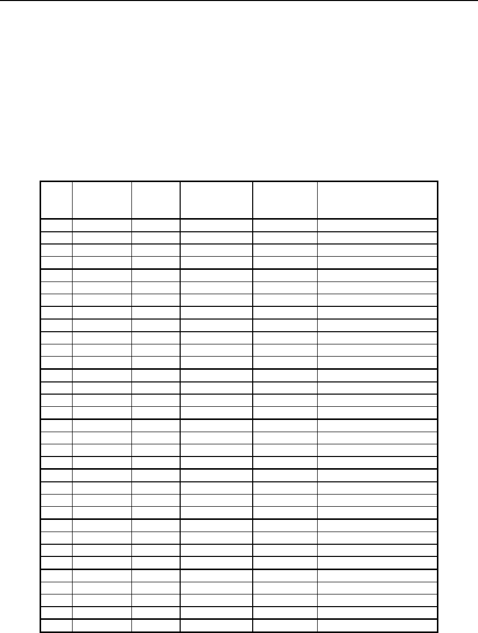
3.3 Relay Input Connections -- J2
The relay input connections appear on a 50-pin female micro-ribbon telco style
connector, J2. The relay input connector is laid out to match the MCN IOB
module pin-for-pin. J2 can be connected to the IOB module directly through a 25-
pair straight-through male to male cable.
Since the MCN CIB module was originally set up to match the Digitac P805
pinout, the signals are a bit scrambled. For convenience, the pinouts are as shown
in two tables, the first sorted by relay and function, and the second sorted by pin
number. The corresponding signal names for the CIB and IOB modules are also
shown.
J2
Pin
Relay I/O Bit Relay Board
Function
CIB
Module
Signal
IOB Mode 1 Signal
21 1 1 Input/Output VOTE 1 Input/Output 1
22 1 2 Output RECEIVE 1 Input 1
20 1 3 Input/Output DISABLE 1 Input/Output 9
23 1 4 Output FAIL 1 Input 9
46 2 1 Input/Output VOTE 2 Input/Output 2
47 2 2 Output RECEIVE 2 Input 2
45 2 3 Input/Output DISABLE 2 Input/Output 10
48 2 4 Output FAIL 2 Input 10
15 3 1 Input/Output VOTE 3 Input/Output 3
16 3 2 Output RECEIVE 3 Input 3
14 3 3 Input/Output DISABLE 3 Input/Output 11
17 3 4 Output FAIL 3 Input 11
40 4 1 Input/Output VOTE 4 Input/Output 4
41 4 2 Output RECEIVE 4 Input 4
39 4 3 Input/Output DISABLE 4 Input/Output 12
42 4 4 Output FAIL 4 Input 12
9 5 1 Input/Output VOTE 5 Input/Output 5
10 5 2 Output RECEIVE 5 Input 5
8 5 3 Input/Output DISABLE 5 Input/Output 13
11 5 4 Output FAIL 5 Input 13
34 6 1 Input/Output VOTE 6 Input/Output 6
35 6 2 Output RECEIVE 6 Input 6
33 6 3 Input/Output DISABLE 6 Input/Output 14
36 6 4 Output FAIL 6 Input 14
3 7 1 Input/Output VOTE 7 Input/Output 7
4 7 2 Output RECEIVE 7 Input 7
2 7 3 Input/Output DISABLE 7 Input/Output 15
5 7 4 Output FAIL 7 Input 15
28 8 1 Input/Output VOTE 8 Input/Output 8
29 8 2 Output RECEIVE 8 Input 8
27 8 3 Input/Output DISABLE 8 Input/Output 16
30 8 4 Output FAIL 8 Input 16
1 Common Ground Ground Ground
Table 6 - Relay Inputs Connector J2 Pinout -- Sorted by Relay & Function