MCN Monitoring and Control Network Comparator Display System TSAM Interface Module TIB Hardware Reference Manual S2-60469-100 68-10911-100
FCC Statement This equipment has been tested and found to comply with the limits for a Class A digital device, pursuant to Part 15 of the FCC Rules. These limits are designed to provide reasonable protection against harmful interference when the equipment is operated in a commercial environment. This equipment generates, uses, and can radiate radio frequency energy and, if not installed and used in accordance with the instruction manual, may cause harmful interference to radio communications.
TIB Hardware Reference CTI Products, Inc. Standard Limited Hardware Warranty LIMITED WARRANTY. Equipment manufactured by CTI Products, Inc. is warranted to be free from defects in material and workmanship for a period of ONE (1) YEAR from date of shipment to original purchaser. Under this warranty, our obligation is limited to repairing or replacing any equipment proved to be defective by our inspection within one year of sale to the original purchaser.
TIB Hardware Reference CTI Products, Inc. CTI Products, Inc. 1211 W. Sharon Rd. Cincinnati, OH 45240 If you have questions about the MCN comparator display system, call us at: (513) 595-5900.
TIB Hardware Reference CTI Products, Inc. 1. INTRODUCTION..................................................................................................................... 1 1.1 REFERENCE DOCUMENTS ........................................................................................................... 1 2. SPECIFICATIONS................................................................................................................... 2 3. THEORY OF OPERATION...........................................
TIB Hardware Reference CTI Products, Inc. 1. Introduction Introduction The TSAM Interface Module (TIB) is a member of the Monitoring and Control Network (MCN™) family of auxiliary modules. Hardware specifications, special installation, and configuration information are described in this manual. The TIB module is a control module that interfaces between a CIB module and CTI Product’s Transmitter Steering Audio Matrix (TSAM).
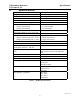
TIB Hardware Reference CTI Products, Inc. 2. Specifications Specifications Size Weight Temperature Humidity Module Power Number of Transmitters Supported Open Circuit Voltage (all I/O pins) jumper E1B removed jumper E1B installed Inputs per Transmitter active low, pull-up to +5 or +13.
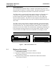
TIB Hardware Reference CTI Products, Inc. Specifications Figure 2 shows the equivalent circuits of the TIB I/O pins. The pull-up voltage Vp by jumper E1B, located on the rear of the module. • Vp = 13.8 Vdc with jumper E1B out • Vp = 5.0 Vdc with jumper E1B in Vp +5V 22K HCMOS IC INPUT 150K ESD PROTECTION 0.1uF 30V TRANSORB INPUT +5V 180K Vp 22K ESD PROTECTION 0.1uF 30V TRANSORB OUTPUT Vp 22K ESD PROTECTION +5V HCMOS IC INPUT 30V TRANSORB 150K 0.
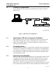
TIB Hardware Reference CTI Products, Inc. 3. Theory of Operation Theory of Operation This section describes the operation of the TIB module in an MCN comparator display system. LOCAL PC COMPARATOR OUT COM 2 COM 1 HIB IN IN OUT T CIB 1 VOTE LINES P/S TX SELECT IN T OUT TIB FORCE SELECT TSAM CA-80119-100 Figure 3 - Basic System Configuration 3.
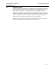
TIB Hardware Reference CTI Products, Inc. 3.4 Theory of Operation Receiver Banks If the Comparator I/O Module that is associated with a TIB supports more than 8 receivers (it divides its receivers into multiple banks, as specified in the Receiver Banks section of reference 1), then the TIB must be configured so that its transmitters are associated with the proper receiver bank of the Comparator I/O Module.
TIB Hardware Reference CTI Products, Inc. 4. Option Switches Option Switches Three sets of option switches are provided for module configuration. The module must be power cycled or reset after these switches are set so that the options will take effect. Table 2 describes the option switches and shows the factory defaults.
TIB Hardware Reference CTI Products, Inc. Option Switches A TIB can monitor 8 receivers (one receiver bank) for FORCE VOTE information. Option switches 1 through 3 allow the TIB to associate its 8 transmitters with any receiver bank supported by the Comparator I/O Module. The settings for these switches is shown in Table 3.
TIB Hardware Reference CTI Products, Inc. Option Switches Jumper E1A is located across the top 2 terminals of the 6 pin terminal block. Jumper E1B is located across the left side middle and bottom terminals of the 6 pin terminal block. The remaining 2 terminals of the block are unused. Jumper E1A E1B Function Reserved In for inputs pulled up to +5 Vdc. Out for inputs pulled up to +13.8 Vdc.
TIB Hardware Reference CTI Products, Inc. 5. Connectors Connectors The NETWORK IN/OUT ports on the front of the TIB are used to connect the TIB with other MCN modules. These ports carry both the network data signals as well as DC power for power distribution with other modules. Table 4 gives the pinout for these connectors. Figure 6 shows the location of pin 1 for each port. PRODUCTS, INC.
TIB Hardware Reference CTI Products, Inc. Connectors Connector J1 provides the discrete I/O for the TSAM interface. Table 6 gives the pinout for this connector. Table 5 describes the functions of the I/O signals. Signal TX Select Out Direction Input/Output Tx Select In Force Select Input Output Description Activated to select the transmitter to steer to. This signal is used as an Output only. Ground input to indicate the active transmitter(s).
TIB Hardware Reference CTI Products, Inc.
TIB Hardware Reference CTI Products, Inc. 6. Mounting Mounting Refer the reference 1, section Mounting Options, for details about mounting the TIB module. CAUTION Make sure that any mounting screws used to secure unit to a bracket do not protrude into the unit’s enclosure more than 1/8 inches from the bottom surface of the unit. Using a larger screw that touches the PC board inside the unit may damage the unit when it is powered. Doing so will void the unit’s warranty.
TIB Hardware Reference CTI Products, Inc. Comparator Wiring Lists 7. Special Installation Instructions 7.1 Unit Address Setting A TIB must be programmed with two unit addresses: 1. the address of the CIB it will operate with 2. the TIB’s own address You only need to perform this programming once, at installation time.
TIB Hardware Reference CTI Products, Inc. Comparator Wiring Lists For example, Figure 7 shows a system with a single TIB and CIB. The following steps show how the system might be setup, using the following address assignments: • CIB address is Group 00, Module 0 • TIB address is Group 01, Module 0 • HIB address is Group 80, Module 0 (this is set using the MCNCFG program running on the Local PC) Step 1 2 3 4 5 6 7 7 8 9 10 11 12 Action Connect the module’s NETWORK IN and OUT ports as shown in the diagram.
TIB Hardware Reference CTI Products, Inc. 8. Wiring a TIB to a TSAM Wiring a TIB to a TSAM Table 7 provides the wiring list to connect a TIB module to a TSAM.
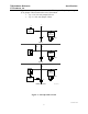
TIB Hardware Reference CTI Products, Inc. System Examples 9. System Examples 9.1 Basic System Operation Figure 8 shows an example system using the TIB module and a TSAM.
TIB Hardware Reference CTI Products, Inc. System Examples voted and that transmitter 8 is active. Both of these states will be shown on the operator’s PC. To force the TSAM to steer to transmitter 1, the operator will generate a FORCE VOTE for receiver 1. The TIB will receive this FORCE VOTE for receiver 1 and setup the Tx Select lines for transmitter 1 and the Force Select line. When the TIB activates the Force Select line to the TSAM, the TSAM will immediately steer to transmitter 1.
TIB Hardware Reference CTI Products, Inc. • • • • • System Examples Because all of the receivers and transmitters are on the same communication channel, TSAM 1 and TSAM 2 are connected together through their P103 expansion ports. The system transmitters are connected to the TSAMs. Transmitters 1 through 8 are connected to TSAM 1 and transmitters 9 through 16 are connected to TSAM 2. TIB 2’s Force Select line is connected to TIB 1’s Force Select line, not to TSAM 2’s Force Select line.
TIB Hardware Reference CTI Products, Inc. 10. Troubleshooting Troubleshooting This table is a list of troubleshooting tips specific to the TIB module. For additional troubleshooting tips, refer to the troubleshooting section found in the Monitoring and Control Network System Manual, reference 1. Due to the high percentage of surface-mount components the TIB is treated as a field replaceable unit.