
User guide
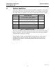
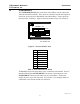
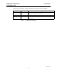
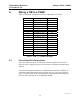
Table Of Contents

TIB Hardware Reference Option Switches
CTI Products, Inc.
68-10911-100
6
4. Option Switches
Three sets of option switches are provided for module configuration. The module
must be power cycled or reset after these switches are set so that the options will
take effect. Table 2 describes the option switches and shows the factory defaults.
SWITCH DESCRIPTION DEFAULT
GROUP unit address setting (00-FE)
refer to the MCN System Manual
00
MODULE unit address setting (0-F)
refer to the MCN System Manual
0
OPTION
position 1 receiver bank selector 1 (see Table 3)
DOWN
position 2 receiver bank selector 2 (see Table 3) DOWN
position 3 receiver bank selector 3 (see Table 3) DOWN
position 4 unit address selector DOWN
Table 2 - TIB Option Switches
The Group and Module selector switches are used to set the node address during
module installation. Refer to the Monitor and Control Network System Manual
for details about setting these switches.
The unit address selector switch (OPTION switch position 4) is only used at
installation time. Refer to section 7, Special Installation Instructions, for a
description of this switch. For normal operation, this switch must be in the
DOWN position.