Transmitter Steering Audio Matrix Installation & Maintenance Manual S2-60477-210 April 18, 2003 Information contained in this document is subject to change without notice and does not represent a commitment on the part of CTI Products, Incorporated. The software described in this document is furnished under a license agreement. The software may be used or copied only in accordance with the terms of the agreement.
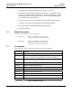
TSAM Installation and Maintenance CTI Products, Inc. Revision 2.10 Table of Contents 1. System Description ......................................................................................................1 1.1 1.2 1.3 1.4 TSAM Features ...................................................................................................................1 Model Description ..............................................................................................................2 Feature Breakdown ...
TSAM Installation and Maintenance CTI Products, Inc. Revision 2.10 Table of Contents 4.2.1 4.2.2 4.2.3 4.3 4.4 4.4.1 4.4.2 4.5 Expansion Cables..................................................................................................................... 19 Expansion TSAM Addressing & Jumpers ............................................................................... 20 Expansion Unit Programming..................................................................................................
TSAM Installation and Maintenance CTI Products, Inc. Revision 2.10 Table of Contents 5.8.7 5.9 5.9.1 5.9.2 Simplex PTT Release Mask Timer Programming....................................................................53 Expansion and Home Transmitter Parameters..................................................................54 Expansion Units .......................................................................................................................54 Home Transmitter Selection ............
TSAM Installation and Maintenance CTI Products, Inc. Revision 2.10 Table of Contents 9.2.1 9.2.2 9.3 All Control Signals EXCEPT "Console 1,2 PTT Out" ............................................................ 72 Console 1,2 PTT Out Control Signals ..................................................................................... 73 Physical and Environmental ............................................................................................. 73 10. Parts List Main Board (TSAM-T1) .......
TSAM Installation and Maintenance CTI Products, Inc. Revision 2.10 Table of Figures Figure 1 Typical System Diagram ................................................................................................................. 1 Figure 2 TSAM Audio Path Diagram............................................................................................................ 4 Figure 3 Repeater Ping-Pong Operation with End of Receive Mode ............................................................
TSAM Installation and Maintenance CTI Products, Inc. Revision 2.10 Default Programmable Options Changes Version 1.60 Programming Option Previous Default Value Rev 1.60 Default Value 60 ms 120 ms First RX Integrated Vote Off 15 seconds High Level Guard Tone Duration Steering Rules Transmitter Revert Time Default Programmable Options Changes in Version 1.70 Programming Option Previous Default Value Rev 1.
TSAM Installation and Maintenance Rev. 2.10 CTI Products, Inc. 1. Chapter 1 System Description System Description Transmitter steering radio systems consist of multiple strategically located transmitters and receivers. When a mobile or portable calls the dispatcher, the system comparator selects the receiver with the best signal. The CTI Transmitter Steering Audio Matrix (TSAM) monitors this information to determine the best site for the next transmission.
TSAM Installation and Maintenance Rev. 2.10 CTI Products, Inc. 1.2 Chapter 1 System Description • A transmitter may be manually selected via a "force" override. • Optional Secondary Mode operation, which removes a single base station site from the voting scheme and locks it on an alternate frequency, using internally generated frequency select tones. Audio is automatically routed to a secondary base station interface. • Two tone generators, one for main and one for secondary mode operation.
TSAM Installation and Maintenance Rev. 2.10 CTI Products, Inc. 1.4 Chapter 1 System Description Feature Breakdown The "xxx" in the model number indicates the version number of the unit.
TSAM Installation and Maintenance Rev. 2.10 CTI Products, Inc. 1.5 Chapter 1 System Description TSAM Audio Switching Transmit Audio from the radio control console microphone enters the TSAM through the Console 1 (Main--Steered Channel) and Console 2 (Secondary Channel) audio line inputs. A PTT signal for both Console 1 and 2 is also connected to the TSAM. When an operator keys the Main channel, transmit audio from the console is routed through the TSAM to the steered transmitter line output.
TSAM Installation and Maintenance Rev. 2.10 CTI Products, Inc. 2. Chapter 2 Main Channel Operation Main Channel Operation The Main radio channel is the steered radio channel. The TSAM has inputs to monitor the receiver Vote or Select lines from the radio system comparator. The Vote indications are processed to determine the start and end of transmissions from field radios.
TSAM Installation and Maintenance Rev. 2.10 CTI Products, Inc. 2.2.1 Chapter 2 Main Channel Operation Instant Update Mode Instant Update Mode updates the steered transmitter as soon as the Free-vote timer has expired at the beginning of a portable/mobile transmission. It is used only with the First Receiver Vote option enabled. This mode mode is cannot be used with the Smart-Steer™ voting algorithm.
TSAM Installation and Maintenance Rev. 2.10 CTI Products, Inc. Chapter 2 Main Channel Operation Since the Smart-Steer algorithm does not complete vote processing until the end of current receiver activity, it must use the End of Receive Update Mode. 2.2.3 Instant Update Input This input can be used to switch between End of Receive Update Mode and Instant Update Mode from the console. To do this, program the TSAM for End of Receive Update Mode.
TSAM Installation and Maintenance Rev. 2.10 CTI Products, Inc. 2.3 Chapter 2 Main Channel Operation Initial Transmitter Selection Options If you have made it this far in the manual, you're probably saying, "Okay, I understand how the Instant Update and End of Receive Update Modes work, but what happens after the system has been quiet for a while? Which transmitter is used?" (At least I thought I heard you say that.
TSAM Installation and Maintenance Rev. 2.10 CTI Products, Inc. Chapter 2 Main Channel Operation range is interpreted as off and will display as revert off on the screen. Numbers outside the range of 5 to 65535 will produce an out of range error, and you will be prompted again to enter a value in the correct range. 2.3.2 Dynamic Update Mode (TSAM Version 1.20 and up) Dynamic update mode is used in conjunction with the EOR (End of Receive Update Mode) and Integrated Vote mode.
TSAM Installation and Maintenance Rev. 2.10 CTI Products, Inc. 2.4 Chapter 2 Main Channel Operation Simplex Operation In simplex systems, the voting receivers will hear the base station transmitters. If the comparator is active during this time, the TSAM must be instructed to ignore any voting activity. This is done by programming the ‘ Sense RX activity during Console 1 PTT’ option is set to ‘ N’ This is found under the TX Steering menu.
TSAM Installation and Maintenance Rev. 2.10 CTI Products, Inc. 2.5.1 Chapter 2 Main Channel Operation Repeater Operation with various Steering Algorithms The steering update mode used determines how repeater keying takes place in the TSAM. The TSAM uses Instant and End of Receive Update modes. The Smart-Steer algorithm always uses the EOR update mode. First RX steering uses either Instant update or EOR update modes. Repeater keying in each of these modes is described in the following sections. 2.5.1.
TSAM Installation and Maintenance Rev. 2.10 CTI Products, Inc. 2.5.2.2 Chapter 2 Main Channel Operation Repeater Hang Time with EOR Update Mode For EOR updated modes, the TSAM steers to the proper site for the next transmission when the current transmission ends. If no site change occurs, the current site remains keyed for the duration of hang time. If a site change does occur, the current site is unkeyed and the new site is keyed. It remains keyed for the duration of hang time.
TSAM Installation and Maintenance Rev. 2.10 CTI Products, Inc. 2.5.6 Chapter 2 Main Channel Operation Console Priority with Repeater Systems In a typical transmitter steering repeater system, a transmitter is keyed from two different sources. Detection of a received signal will key a transmitter so it can be "repeated", and the systems dispatcher will key the transmitter from the dispatch console. In many systems, it is required for the dispatcher to have priority access to the steered transmitter.
TSAM Installation and Maintenance Rev. 2.10 CTI Products, Inc. 2.6 Chapter 2 Main Channel Operation Multicast Options Unit Versions 1.70 and up / Units with Secondary System Capability Only The Multicast feature allows the dispatcher to key a number of transmitters simultaneously on the main channel for system-wide announcements. When the latched Multicast input is active and the console is keyed, the Transmitter Steering System keys all transmitters that are programmed for Multicast operation.
TSAM Installation and Maintenance Rev. 2.10 CTI Products, Inc. 3. Chapter 3 Secondary Channel Operation Secondary Channel Operation Only available on TSAM units with Secondary Option One unique feature of the TSAM is that it allows a properly equipped steered base station (receiver/transmitter pair) to be removed from the transmitter steering system and operate as an independent base/repeater on a second channel. The secondary TSAM channel looks like and additional channel to the system console.
TSAM Installation and Maintenance Rev. 2.10 CTI Products, Inc. 3.1 Chapter 3 Secondary Channel Operation Secondary Site Selection The TSAM automatically completes the following steps when a dispatcher selects a secondary site. Secondary Operation is initiated when the TSAM detects a non-zero secondary site on the binary active low Site Select inputs. If the site is currently voted, the receiver is immediately disabled, forcing the receive comparator to re-vote.
TSAM Installation and Maintenance Rev. 2.10 CTI Products, Inc. 3.2 3.3 Chapter 3 Secondary Channel Operation Secondary Site Select "Off" 1. This function terminates secondary operation and returns the secondary base to the Main steered channel. 2. Secondary Operation is terminated when all secondary select inputs return high (active low inputs). 3. The TSAM mutes C2 RX Audio. 4. The TSAM sends the F1 frequency change tone sequence to the secondary base. 5.
TSAM Installation and Maintenance Rev. 2.10 CTI Products, Inc. 3.4.1 Chapter 3 Secondary Channel Operation Momentary PL Monitor Control When the Monitor input is momentarily activated, the TSAM sends a PL Monitor tone out the selected Secondary site. The station re-enables the PL decoder on the next transmission. 3.4.2 Sustained PL Monitor Control When the Monitor input is activated, the TSAM sends a PL Monitor tone out the selected Secondary site.
TSAM Installation and Maintenance Rev. 2.10 CTI Products, Inc. 4. Chapter 4 Installation Installation Installation of the TSAM consists of: 4.1 • Pre-setting jumper options • Mounting the unit in a cabinet • Routing the 25 pair control and audio cable(s) to the cross-connect panel • Routing the power cable • Programming the options • Setting the system transmit and receive audio levels.
TSAM Installation and Maintenance Rev. 2.10 CTI Products, Inc. 4.2.2 Chapter 4 Installation Expansion TSAM Addressing & Jumpers Address switch SW102 on the front of the TSAM is used to set TSAM SPI bus addresses. A Master TSAM always has address 0. Additionally, the Master TSAM drives the Main and Secondary channel expansion transmit audio busses and receives audio on the Main and Secondary channel receive audio expansion busses. Slave TSAM units have addresses 1-7.
TSAM Installation and Maintenance Rev. 2.10 CTI Products, Inc. 4.2.3 Chapter 4 Installation Expansion Unit Programming When a system is programmed for a slave (expansion) TSAM and the slave unit is disconnected, the system must be reprogrammed to insure proper operation. If you must run a system with an expansion unit disconnected, re-program the master TSAM for one less expansion unit. Be sure that the expansion units are addressed sequentially. 4.
TSAM Installation and Maintenance Rev. 2.10 CTI Products, Inc. 4.4 Chapter 4 Installation P101 (TX) Cable Signals This male connector is present on all units. The TX cable contains all of the transmit audio line outputs and control signals.
TSAM Installation and Maintenance Rev. 2.10 CTI Products, Inc. 4.4.
TSAM Installation and Maintenance Rev. 2.10 CTI Products, Inc. 4.5 Chapter 4 Installation P201 (RX) Cable signals This male connector is present only on units with Secondary Mode. It contains all receive audio line inputs, control inputs for secondary operation, and a few other functions.
TSAM Installation and Maintenance Rev. 2.10 CTI Products, Inc. 4.5.1 4.5.2 Chapter 4 Installation P201 Secondary Channel Signal Definitions Console 2 M Keying (/PTT) (C2PTT) Logic signal from Console Low = PTT on Secondary channel Disable RX 1 - 8 Logic Output to Comparator Low to disable receiver slot during Secondary operation Console 2 PTT Out COM & N.O Relay contacts active when C2PTT is active.
TSAM Installation and Maintenance Rev. 2.10 CTI Products, Inc. 4.6 Chapter 4 Installation TX Select Console Wiring -- Diode Matrix Plug / Schematic The Diode Matrix Plug is available as an accessory to the TSAM. It can be used to interface consoles with simple Inputs & Outputs with the bi-directionsl TSAM TX Select lines.
TSAM Installation and Maintenance Rev. 2.10 CTI Products, Inc. 4.
TSAM Installation and Maintenance Rev. 2.10 CTI Products, Inc. 4.8 Chapter 4 Installation Receiver to Transmitter Mapping with Diode Matrix Some systems have more receiver sites than transmitter sites. In these systems you must map each receiver to one transmitter. A diode matrix is used to allow multiple Voted comparator outputs to drive a single RX Voted line on the TSAM unit.
TSAM Installation and Maintenance Rev. 2.10 CTI Products, Inc. 4.9 Chapter 4 Installation Secondary Site & Frequency Control Wiring The Secondary Site Select and Frequency Select inputs are binary coded. If your console will not generate binary coded outputs, you will have to generate the binary signals from a "1 of N" output from the console. An 8-site 5-frequency system in the following figure.
TSAM Installation and Maintenance Rev. 2.10 CTI Products, Inc. 4.10 Chapter 4 Installation Secondary Site Select Table The Secondary Site Select inputs are binary coded, active low. The following table shows the Secondary Site Select inputs.
TSAM Installation and Maintenance Rev. 2.10 CTI Products, Inc. 4.11 Chapter 4 Installation Secondary Frequency Tone Table The following table shows the relationship between the secondary frequency inputs, the secondary channel frequencies, and the base station frequencies.
TSAM Installation and Maintenance Rev. 2.10 CTI Products, Inc. 4.12 Chapter 4 Installation Initial System Checkout A system block diagram for a system with secondary operation is shown in Figure 12. As can be seen from studying the diagram, the TSAM connects to the following system equipment: The steered base stations and receivers, the system comparator, the Centracom Series II console, and Smartswitch II controller. Your system connection will vary, depending upon system equipment.
TSAM Installation and Maintenance Rev. 2.10 CTI Products, Inc. 4.13 Chapter 4 Installation Front Panel Indicators The TSAM has several front panel LED indictors used to display operational status and diagnostic information. Reset This indicator lights when the reset line is held low. This LED should be lit when the front panel reset button is pressed or the TSAM is initially powered. Vote The vote led indicates the start of the steering process.
TSAM Installation and Maintenance Rev. 2.10 CTI Products, Inc. 4.14 Chapter 4 Installation Main Channel Checks Proper connection of the TSAM Main channel controls is verified by performing the system checks that follow. Note: The following test is intended as a quick verification of basic system functions. A comprehensive system test must be performed after final installation and level setting is complete.
TSAM Installation and Maintenance Rev. 2.10 CTI Products, Inc. 4.
TSAM Installation and Maintenance Rev. 2.10 CTI Products, Inc. Chapter 4 Installation RX Audio Input Wiring Audio from the remote receiver sites connects to the TSAM RX line inputs. A high impedance audio input allows audio to be bridged directly across the RX audio inputs of the comparator. The audio inputs are used for secondary channel mode. In this mode, the comparator receiver input is disabled.
TSAM Installation and Maintenance Rev. 2.10 CTI Products, Inc. 5. Chapter 5 Setting Programmable Options Setting Programmable Options Many TSAM operational parameters are set in software. To edit these programmable options, connect a dumb terminal (or a PC with a terminal emulator) to the TSAM programming port. 5.1 Terminal Connections & Settings TSAM Programming Port 5.
TSAM Installation and Maintenance Rev. 2.10 CTI Products, Inc. Chapter 5 Setting Programmable Options Main Menu Main Menu Commands: A Edit High Level Guard Tone Parameters F Fetch Defaults M Edit Multicast Parameters N Edit Function Tone Parameters R Edit Repeater Parameters S Edit Secondary Operation Options T Edit Transmitter Steering Options X Edit Expansion & Home Transmitter Parameters H or ? Help Q Quit : Enter the menu command to gain access to the desired option menu. 5.
TSAM Installation and Maintenance Rev. 2.10 CTI Products, Inc. 5.
TSAM Installation and Maintenance Rev. 2.10 CTI Products, Inc. 5.5.2 Chapter 5 Setting Programmable Options Coded (Encrypted) TX operation The TSAM unit supports Coded (encrypted) operation under the following conditions: • The encryption and decryption must be done at the base stations. • The base station automatically passes clear or decrypted audio as appropriate. • The base station audio control lines must always pass clear audio.
TSAM Installation and Maintenance Rev. 2.10 CTI Products, Inc. 5.5.2.1 Chapter 5 Setting Programmable Options Coded / Clear using Positive Mode Control Keying This option works with Main (Steered) system and the Secondary system (if used). The TSAM can be programmed to generate two function tones in a tone control sequence. This is called positive mode control (PMC). PMC is used in some Motorola radio systems for controlling encrypted and clear mode keying.
TSAM Installation and Maintenance Rev. 2.10 CTI Products, Inc. 5.5.2.2 Chapter 5 Setting Programmable Options Coded / Clear using Single Function Tone Keying Works with Main (Steered) system only. The TSAM can be programmed to control the Coded or Clear TX in a base station on the Main (steered) system with a single function tone (versus the dual function tone PMC).
TSAM Installation and Maintenance Rev. 2.10 CTI Products, Inc. 5.6.
TSAM Installation and Maintenance Rev. 2.10 CTI Products, Inc. 5.6.2 Chapter 5 Setting Programmable Options L: Listing Enabled Multicast Transmitters You can list the enabled multicast transmitters with the L command as shown below. There is a matrix of 8 transmitters and 8 TSAM units.
TSAM Installation and Maintenance Rev. 2.10 CTI Products, Inc. 5.6.3 Chapter 5 Setting Programmable Options EA Enabling All transmitters for multicast If you want to enable all transmitters for multicast, use the EA (Enable All) command as shown.
TSAM Installation and Maintenance Rev. 2.10 CTI Products, Inc. 5.6.4 Chapter 5 Setting Programmable Options EI: Enabling Individual transmitters for multicast Use the EI command to enable individual transmitters for multicast. The EI command lets you enter a number of transmitters if you wish. End each entry with a (). When you are finished adding transmitters, enter a 0 for the transmitter number. You can see the results with the L (List) command.
TSAM Installation and Maintenance Rev. 2.10 CTI Products, Inc. 5.6.5 Chapter 5 Setting Programmable Options DA: Disabling All transmitters for multicast Use the DA (Disable All command to disable all Multicast transmitters.
TSAM Installation and Maintenance Rev. 2.10 CTI Products, Inc. 5.6.6 Chapter 5 Setting Programmable Options DI: Disabling individual transmitters for multicast Use the DI command to disable individual transmitters for multicast. The DI command lets you enter a number of transmitters if you wish. End each entry with a (). When you are finished deleting transmitters, enter a 0 for the transmitter number. You can see the results with the L (List) command.
TSAM Installation and Maintenance Rev. 2.10 CTI Products, Inc. 5.6.7 Chapter 5 Setting Programmable Options Q: Quitting the Multicast Menu Use the Q (Quit) command to exit from the Multicast programming menu. You will be asked if you want to write the changes to EEPROM or if you want to Abort.
TSAM Installation and Maintenance Rev. 2.10 CTI Products, Inc. 5.7 Chapter 5 Setting Programmable Options Secondary Channel Options Enter the Secondary Options menu with an “S” from the main menu. 5.7.1 Debounce Time Selecting the secondary site and frequency may cause the TSAM control inputs to change several times before the desired site and frequency are set, especially if the console uses a scrolling control.
TSAM Installation and Maintenance Rev. 2.10 CTI Products, Inc. 5.8 Chapter 5 Setting Programmable Options Transmitter Steering Options The Transmitter Steering menu is shown below.
TSAM Installation and Maintenance Rev. 2.10 CTI Products, Inc. Chapter 5 Setting Programmable Options Forced Site Select Hold Time When a transmitter is manually forced, the TSAM keeps that site as the steered site for the Forced Site Select Hold Time, regardless of system receiver activity. Hold Time values can be programmed from 0 to 32,767 msec and to Next Vote. When set to Next Vote, the current site is held until current vote activity ceases and new activity is detected.
TSAM Installation and Maintenance Rev. 2.10 CTI Products, Inc. 5.8.4 Chapter 5 Setting Programmable Options Instant Update / End of Receive Update If the Smart-Steer Integrated vote mode is selected, the TSAM automatically forces the End of Receive (EOR) Update mode. If the First Receive steering is selected, you have the option of using Instant Update or End of Receive Update modes: First RX / Integrated Vote steering rules (F/I) = (I) I : F Instant Update or End of RX Update (I/E) = (I) I : I 5.8.
TSAM Installation and Maintenance Rev. 2.10 CTI Products, Inc. 5.9 Chapter 5 Setting Programmable Options Expansion and Home Transmitter Parameters :X Expansion & Home Transmitter Parameters: To accept (DEFAULT) value: type or . To accept CURRENT value: type . To change: type desired value then . Number of Expansion TSAM boards present (max = 7) = (0) 0 : HOME A Transmitter = (1) 1 : 1 HOME B Transmitter = (2) 2 : 2 Finished. 5.9.
TSAM Installation and Maintenance Rev. 2.10 CTI Products, Inc. 6. Chapter 7 Tone Timing Diagrams Level Setting After the physical TSAM installation and initial cabling checkout have been completed, all system levels should be measured and adjusted as necessary. When setting up the TSAM, make all level measurement either directly on the audio input or output lines, or from the metering test points that are accessible from the front panel of the TSAM.
TSAM Installation and Maintenance Rev. 2.10 CTI Products, Inc. 6.2.1 Chapter 7 Tone Timing Diagrams Motorola Centracom Series II Consoles Set the average transmit audio level of the Centracom console to -10 dBm as outlined below. This level provides proper operation with the TSAM when the TSAM is adjusted according to the procedure below. No additional adjustment to the Centracom console are necessary.
TSAM Installation and Maintenance Rev. 2.10 CTI Products, Inc. Chapter 7 Tone Timing Diagrams Manually force select TX 1 from the console by pressing the force site select button, or manually select TX 1 by force voting the system comparator long enough for the TSAM to steer to that site. The time will vary depending on system settings; 2 seconds is normally sufficient. 6.3.3 Centracom Series II Generate a console test tone by resetting the Main channel BIM.
TSAM Installation and Maintenance Rev. 2.10 CTI Products, Inc. 6.5 Chapter 7 Tone Timing Diagrams Console 1 RX Audio Output Adjustment The Console 1 RX Audio line has receive audio for the currently steered site. The currently steered site is not always the same as the currently voted site. Main channel RX audio is the audio from the system comparator, which is the audio from the currently voted site. In most systems there is no need for Console 1 RX Audio from the TSAM, and it is left unconnected.
TSAM Installation and Maintenance Rev. 2.10 CTI Products, Inc. Chapter 7 Tone Timing Diagrams 7. Tone Timing Diagrams 7.
TSAM Installation and Maintenance Rev. 2.10 CTI Products, Inc. 7.2 Chapter 7 Tone Timing Diagrams PL Monitor / Enable Tones (No TX) The following figure shows the PL Monitor tone sequence in Sustained Mode.
TSAM Installation and Maintenance Rev. 2.10 CTI Products, Inc. 8. Chapter 8 Maintenance Theory Maintenance Theory The TSAM is just one component in a sophisticated radio control system. The maintenance information is intended to allow field service personnel to quickly isolate faults to the TSAM subsystem. Further information is provided to allow a problem to be isolated to a particular TSAM board. The board may then be changed in the field.
TSAM Installation and Maintenance Rev. 2.10 CTI Products, Inc. 8.2 Chapter 8 Maintenance Theory Transmitter Board Electronics The TSAM-T1 board contains the following subsystems: TSAM-T1 Transmitter Board • • • • • • • • 8.2.1 Power Supply Microcontroller Unit Programming Port Interface Serial I/O Bus (SPI) Logic I/O circuitry Console TX audio line receivers TX audio switching TX line drivers Power Supply The TSAM requires a nominal 20-24V AC or 24V DC power source. Power is fed from J101.
TSAM Installation and Maintenance Rev. 2.10 CTI Products, Inc. 8.2.2 Chapter 8 Maintenance Theory Audio circuitry power supply All audio circuitry uses a mid supply audio reference. This audio reference supply is 6.3 Volts with respect to chassis ground. This reference is the audio ground. Care should be taken not to tie audio ground and chassis ground together. This will short the audio 6.3V supply and severely distort all audio signals.
TSAM Installation and Maintenance Rev. 2.10 CTI Products, Inc. Chapter 8 Maintenance Theory Each SPI transfer or command ends with the SPI command data. The last 8 bits of data shifted out on MOSI MCU line are loaded in the command shift register. These 8 bits contain the TSAM board address and command data.
TSAM Installation and Maintenance Rev. 2.10 CTI Products, Inc. 8.2.4 Chapter 8 Maintenance Theory Transmitter Audio Circuitry Transmit audio from the console's Main and secondary channels connects to the Master TSAM. The TX audio line receivers match the line impedance, and adjust the input audio to the proper level. The line receiver circuit is adjusted so peak input audio is at 0 dBm before the keying tones are inserted.
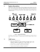
TSAM Installation and Maintenance Rev. 2.10 CTI Products, Inc. 8.2.5 Chapter 8 Maintenance Theory TSAM Expansion Bus The TSAM expansion bus allows up to 8 TSAMs to be connected together to control up to 64 transmitter sites. Expansion connector P103 on the transmitter board allows multiple TSAM to connect together. There are five separate busses on the 26 pin expansion connector. These are the SPI expansion bus, console 1 TX audio, console 1 RX audio, console 2 TX audio, and console 2 TX audio buses.
TSAM Installation and Maintenance Rev. 2.10 CTI Products, Inc. Chapter 8 Maintenance Theory The line receiver amplifier, consisting of IC201D and associated components, amplifies the input signal to the optimum level for the crosspoint switch. Audio into the crosspoint switch is adjusted to a peak level of 0 dBm. This level optimizes signal to noise levels and minimizes cross-talk levels from adjacent wireline inputs. Figure 19 RX Board Audio and I/O Block Diagram 8.3.
TSAM Installation and Maintenance Rev. 2.10 CTI Products, Inc. Chapter 8 Maintenance Theory routed to R300, and finally routed to the C2 RX audio output. This audio is then heard on the console secondary channel speaker. Console Audio Line Outputs Audio that is routed from a receive audio input to the console is amplified by one of the console RX audio line output amplifiers. These amplifiers are functionally equivalent to the TX audio line drivers discussed previously. 8.3.
TSAM Installation and Maintenance Rev. 2.10 CTI Products, Inc. 8.4 Chapter 8 Maintenance Theory Option Jumpers In most instances the TSAM is shipped from the factory with all of the necessary jumper options preset. You should refer to the factory jumper table and verify that the proper options for you system have been selected. Most jumpers can either be accessed by removing the front panels or rear cover plate. This allows changes to be made without removing the TSAM from its rack mounted position.
TSAM Installation and Maintenance Rev. 2.10 CTI Products, Inc.
TSAM Installation and Maintenance Rev. 2.10 CTI Products, Inc.
TSAM Installation and Maintenance Rev. 2.10 CTI Products, Inc. Chapter 9 Hardware Specification 9. Hardware Specification 9.1 Audio Input/Output Electrical Specifications 9.1.1 Power Requirements Parameter Input Voltage Min 20 18 Max 30 24 1.2 24 Input Current Input Power 9.1.2 Units Volts DC Volts AC Amp Watts Audio Inputs -32 to -18 dBm -20 to -6 dBm -8 to +6 dBm 600Ω nominal 10KΩ nominal Input level (600Ω ref.
TSAM Installation and Maintenance Rev. 2.10 CTI Products, Inc. 9.2.2 Chapter 9 Hardware Specification Console 1,2 PTT Out Control Signals Parameter Open circuit voltage Min Max 50 40 100 Switched current 9.3 Physical and Environmental Physical Dimensions Ambient Temperature 19" Rack mount 3.5" high x 15.
TSAM Installation and Maintenance Rev. 2.10 CTI Products, Inc. 10.
TSAM Installation and Maintenance Rev. 2.10 CTI Products, Inc.
TSAM Installation and Maintenance Rev. 2.10 CTI Products, Inc. TSAM-T1 Parts List TSAM_PRT.
TSAM Installation and Maintenance Rev. 2.10 CTI Products, Inc. TSAM-T1 Parts List TSAM_PRT.XLS Reference Symbol Part Number Description RP114 RP113 RP112, 116, 121, 122, 132 RP111 RP108, 109, 110 RP133 4606X-101-472 4610X-101-472 4606X-101-103 4608X-101-103 4610X-101-103 4608X-102-472 4.7k 6 Pin BUSS Rpack 4.7k 10 Pin BUSS Rpack 10k 6 Pin BUSS Rpack 10k 8 Pin BUSS Rpack 10k 10 Pin BUSS Rpack 4.
TSAM Installation and Maintenance Rev. 2.10 CTI Products, Inc. 11. Chapter 11 Parts List Secondary Board (TSAM-R1) Parts List Secondary Board (TSAM-R1) Reference Symbol Part Number Description Capacitors: C217-224, 229, 230, 233, 234, 240, 243, 244, 245 C241, 242, 276-283 C235, 236, 268-275, 284, 285 C231, 232 C225, 249-257, 263-267, 286, 288 140CD50S2-030J 30pF 50V ceramic disc (30) 140CD50S2-047J 1C10C0G102J050B C315C472K1R5CA 1C10Z5U104M050B 47pf 50V ceramic disc (47) .
TSAM Installation and Maintenance Rev. 2.10 CTI Products, Inc. Chapter 11 Parts List Secondary Board (TSAM-R1) Reference Symbol R265, 266 R287, 273, 274, 295, 305 R217-224 R209-216 R269, 270, 275, 276, 290, 291, 293, 294 R292, 300, 301 R283, 284, 285, 303 R280, 281, 282, 296 R225-232 R233-240 R241-248 R249-256 R302 R267, 268 R257-264 RP201-206 RP208, 209 RP207 Part Number 29SJ250-820 29SJ250-1k 29SJ250-2.2k 29SJ250-4.7k 29SJ250-10k Description 820 Ohm .25w 5% carbon film 1k .25w 5% carbon film 2.2k .
TSAM Installation and Maintenance Rev. 2.10 CTI Products, Inc. 12. Revision 1.
Smartswitch II Controller Service Manual CTI Products, Inc. 12.
Smartswitch II Controller Service Manual CTI Products, Inc.
Smartswitch II Controller Service Manual CTI Products, Inc. 12.
Smartswitch II Controller Service Manual CTI Products, Inc. 12.
Smartswitch II Controller Service Manual CTI Products, Inc. 12.
Smartswitch II Controller Service Manual CTI Products, Inc. 13.
Smartswitch II Controller Service Manual CTI Products, Inc.
Smartswitch II Controller Service Manual CTI Products, Inc.
Smartswitch II Controller Service Manual CTI Products, Inc.