MARINE SELF-CONTAINED AIR CONDITIONER CT Models (6,000 | 10,000 | 12,000 | 16,000 | 25,000 BTUs ) INSTALLATION & USER MANUAL CTM-MARINE Please visit http://ctm-marine.com/user-manual/ for the most updated version of this manual. Form No. UM-CT07272022 (866)766 317-5257 +1+1(800) - 5256 info@ctm-marine.com www.ctm-marine.com WARNING Cancer and reproductive Harm www.P65warnings.ca.
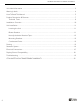
CTM Marine Self-Contained CT Installation & User Manual Unit Label Information ………….……..………………………………………………………………….… 3 Warning Labels …………………………………………………………………………………………….… 4 How To Read This Manual ………………………………………………………………………………….. 5 Product Description & Features ……………………………………………………………………………. 7 Technical Data …………………………………………………………………………………………. 8 Installation Overview ……………………………………………………………………………………… 10 Unit Installation ……………………………………………………………………………………………..
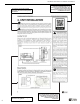
CTM Marine Self-Contained CT Installation & User Manual Unit Label information How To Read Your Label S = Unit With Soft Start H = 208 - 240 V Unit HS = 208 - 240 V Unit With Soft Start Vessel’s water pump minimum requirement Factory Refrigerant Charge *Unit label data changes by model NOTES: 3
CTM Marine Self-Contained CT Installation & User Manual Warning Labels WARNING THIS AIR CONDITIONER UNIT, INCLUDING DUCT WORK, MUST NOT BE INSTALLED IN A FUEL VAPOR AREA OR ENGINE ROOM WHERE ANY POSSIBILITY OF FUEL VAPOR, ENGINE EXHAUST OR ANY OTHER TOXIC GASES MAY EXIST, THIS UNIT IS NOT VAPOR PROOF AND COULD INTRODUCE DEADLY GASED INTO THE LIVING SPACE IF IMPROPERLY INSTALLED. THIS COULD LEAD TO DEATH OR DISABILITY OF THE OCCUPANTS. SEE OWNNER'S MANUAL.
CTM Marine Self-Contained CT Installation & User Manual Please carefully read and follow all safety information and instructions before installing your unit. You may always contact Customer Service at info@ctm-marine.com if you have any doubts, concerns, or questions in connection to your unit or to this Instructions Manual. NOTICE: Failure to strictly follow these warnings and instructions may result in malfunction of the product, death or serious injury.
CTM Marine Self-Contained CT Installation & User Manual Pay attention to signaling symbols throughout this manual with important information. Refer to the illustrations throughout this manual for guidance. 6 Some sections of this instructions manual have QR codes that you can easily scan with your Smartphone. They generally contain tutorial videos following the instructions in this manual or additional information.
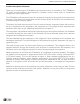
CTM Marine Self-Contained CT Installation & User Manual Product Description & Features Thank you for purchasing our CTM Marine self-contained marine air conditioner. The CTM Marine CT series are self-contained, direct-expansion, seawater cooled, reverse cycle air conditioners designed for marine applications. The CTM Marine self-contained marine air conditioner works by removing heat and moisture from the cabin, which lowers the temperature and the humidity levels.
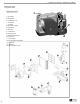
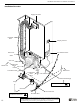
6 7 5 1. Duct Ring 2. Blower/Fan 3. Condenser Coil A. Outflow B. Inflow 4. Blower/Fan Plate 5. Evaporator 6. Air Filter 7. Compressor 8. Reverse Valve 9. Stainless Steel Base 10. Drain Pan 11. Drain Holes 12. Electrical Box Back Plate 13. Capacitor 14. U-Board 15.
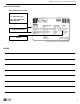
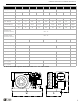
CTM Marine Self-Contained CT Installation & User Manual Model No. CT-6 Capacity (BTU) Voltage (V) CT-6H CT-10 6,000 100-120 CT-10H CT-12 10,000 208-240 100-120 CT-12H CT-16 12,000 208-240 Cycle (Hz) / Phase (Ph) 100-120 CT-16H CT-25H 16,000 25,000 208-240 100-120 208-240 208-240 50-60 / 1 Input: Cool (A) 4.5 2.1 6.7 3.3 8.7 4.3 10.5 5.1 8.5 Input: Heat (A) 5.6 2.7 8.8 3.9 10.8 4.9 13.5 6.6 9.
CTM Marine Self-Contained CT Installation & User Manual Installation Overview Supply Air Grille Insulated Duct Display Control A/C Electrical Box Return Air Grille A/C Unit Water Line Condensate Drain Hose Coil Inflow Hose Condensate Drain Hose Water Line Coil Outflow Hose Overboard Discharge Pump Above the water line Strainer Under the water line 10 ! Shut-Off Valve Thru-Hull Inlet Follow each one of the steps as explained on this manual, any deviation from the procedure explained herein
CTM Marine Self-Contained CT Installation & User Manual Unit Installation Read these instructions completely and then plan all connections which must be made to the a/c unit including ducting, condensate drain line, seawater inlet and outlet hoses, electrical power connection, location of control, and seawater pump placement, to assure easy access for routing and future servicing. NOTICE: Installation and servicing of this system can be hazardous due to system pressure and electrical components.
CTM Marine Self-Contained CT Installation & User Manual Non-Slip Isolation Vibration Tape Your a/c unit comes with a separate non-slip isolator tape design to dampen the vibration caused by the operating a/c unit. Proceed to place the tape on the base of the A/C unit securely. See figure 3. Once this tape is installed care must be taken when moving the a/c unit across mounting surfaces as the tape can be damaged if excessive dragging occurs.
CTM Marine Self-Contained CT Installation & User Manual Ducting Good airflow is critical for the performance of the entire system. It is highly dependent on the quality of the ducting installation. The ducting should be run as straight, smooth and taut as possible minimizing the number of 90° bends (two 90° bends can reduce airflow by 25%). All ducting should: CARBONMONOXIDE HAZARD ! > Do not route ducting through engine room or any area where it may be exposed to dangerous vapors or exhaust fumes.
CTM Marine Self-Contained CT Installation & User Manual Seawater System > The a/c seawater system should Refer to the drawings below for an overview of how the seawater system should look like: have a dedicated thru-hull fitting for the pump. > The inlet for the thru-hull, seacock, hose, and Consider the following instructions when setting up the seawater system of your air conditioning unit. Failure to follow this procedure will void the warranty: strainer should not be smaller than the pump inlet.
CTM Marine Self-Contained CT Installation & User Manual Electrical Connections The following must be observed when making the electrical connections: 1. In accordance with ABYC standard E-8, or equivalent, the Alternating Current (AC) ground (green wire) must be connected to the ground terminal (marked "GRND") on the AC input terminal block of the unit(s) for supply. 2.
CTM Marine Self-Contained CT Installation & User Manual 16 Follow each one of the steps as explained on this manual, any deviation from the procedure explained herein constitutes improper installation of the unit and therefore waives and forever discharges CTM Marine and its subsidiaries from any liability in connection to the installation; use; and functioning of the unit and any and all systems and parts connected to it.
CTM Marine Self-Contained CT Installation & User Manual Follow each one of the steps as explained on this manual, any deviation from the procedure explained herein constitutes improper installation of the unit and therefore waives and forever discharges CTM Marine and its subsidiaries from any liability in connection to the installation; use; and functioning of the unit and any and all systems and parts connected to it.
CTM Marine Self-Contained CT Installation & User Manual Display Control CTM Marine Split System units are compatible with most thermostats currently in the market. Below are the most common thermostats displays used by major marine air conditioner manufacturers.
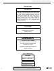
CTM Marine Self-Contained CT Installation & User Manual Troubleshooting Always refer to the user manual of your digital control for troubleshooting as well. PROBLEM POSSIBLE CAUSE POSSIBLE SOLUTION EV handler circuit breaker is OFF. Turn circuit breaker ON at the main vessel’s panel. Wrong wiring terminal strip Check the wiring diagram and make the necessary corrections Input-line Voltage is insufficient. Check power source, either shore or generator power for proper voltage.
CTM Marine Self-Contained CT Installation & User Manual PROBLEM POSSIBLE CAUSE POSSIBLE SOLUTION Temperature set point. Lower temperature to desired temperature on display control. Wrong wiring terminal strip Check the wiring diagram and make the necessary corrections Clean seawater strainer, check for any Obstructed seawater flow obstructions at scoop thru-hull inlet, and check for good steady flow from overboard discharge.
CTM Marine Self-Contained CT Installation & User Manual PROBLEM Fan coil is iced POSSIBLE CAUSE POSSIBLE SOLUTION Supply air is short-cycling Redirect supply air so that is not blowing into the return air stream. Check and seal any leaks in ducting. Humidity to high Close hatches, doors, portholes, to minimize humidity inside the air conditioned cabin. When nothing else works Switch to heat mode to defrost fan coil or use hai dryer.
CTM Marine Self-Contained CT Installation & User Manual CTM LIMITED WARRANTY Air conditioning systems supplied by CTM Marine (hereafter referred to as CTM) are warranted against material and workmanship defects at the time of sale. If it’s determined by CTM, to its satisfaction, that a CTM product contains any material or workmanship defect during the warranty period, then CTM shall repair or replace the CTM product, or refund the original purchase price at CTM’s sole option.
CTM Marine Self-Contained CT Installation & User Manual PRODUCT REGISTRATION The Air Conditioning System can be registered by visiting http://ctm-marine.com/product-registration/. A proof of purchase is required for all Air Conditioning Systems that are not registered.
CTM Marine Self-Contained CT Installation & User Manual You can register your CTM unit or file a claim by visiting www.ctm-marine/warranty or by scanning the code below with your smart device.