TCO2114 P/N 43336 Rev. B V1 5/00 Domestic, Std. Export & European Export Models: TCO21140063 (USA & std. export, 208V) TCO21140066 (USA & std. export, 240V) TCO21140035 (European export, 230V) TCO21140077 (European export, 380-400V) Conveyor Oven Combinations: Single Oven Double Oven (Two-Stack) Triple Oven (Three-Stack) OWNER'S OPERATING & INSTALLATION MANUAL © 2000 CTX, A Middleby Company is a registered trademark of Middleby Marshall, Inc. All rights reserved.
TABLE OF CONTENTS WARNING: IN CASE OF FIRE Disconnect the oven from its power source IMMEDIATELY. Shutting down the electrical heating elements allows the unit to cool, making it easier to put out the fire. SECTION 1 DESCRIPTION .............................................. 3 ENGLISH WARNING: FOR YOUR SAFETY DO NOT STORE OR USE GASOLINE OR OTHER FLAMMABLE VAPORS OR LIQUIDS IN THE VICINITY OF THIS OR ANY OTHER APPLIANCE A. Features ..........................................................
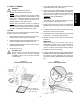
A. FEATURES B. COMPONENT LOCATION AND FUNCTION The Model TCO2114 Mighty Chef Conveyor Oven is designed to quickly and easily cook, bake, and broil a variety of food products with consistent quality and results. The oven is ideal for preparing pizza, garlic toast, cookies, sandwiches, and other food products. Refer to Fig. 1 for the locations of these components. 1-3.Oven controls - see Section 3, Operation. 4. Crumb trays (3 total) - Collect crumbs that pass through the conveyor.
SECTION 2 - INSTALLATION ENGLISH IMPORTANT IT IS THE CUSTOMERS RESPONSIBILITY TO REPORT ANY CONCEALED OR NON-CONCEALED DAMAGE TO THE FREIGHT COMPANY. A. INSTALLATION OPTIONS & KIT AVAILABILITY If the installation will require two or three ovens to be stacked, you must use the separately-available Stacking Kit (P/N T2114STACK). One Kit is required for a two-stack, while two kits are required for a three-stack. Stacking more than three ovens is not permitted. 1. B. ASSEMBLY Installing the Legs a.
SECTION 3 - OPERATION AND FUNCTION OF j. k. The Up Arrow and Down Arrow keys are used to edit cook time and temperature settings. The Preset Menu keys (1-5) are used to select a Preset Menu to change or operate. This section provides a basic description of the Mighty Chef ovens controls, their location, and the functions they perform. The operator MUST be familiar with the controls. See Figure 4. 2. Power On/Off (I/O) switch Switches the oven ON (I) and OFF (O). 1.
C. OPERATION ENGLISH 1. TO PROGRAM A NEW PRESET MENU SELECTION: Perform the procedure in Part E, Programming Preset Menu Selections, in this Section. At least one menu selection MUST be programmed before the oven can be operated. 2. TO TEMPORARILY OVERRIDE A PRESET MENU SELECTION: Perform the procedure in Part E, Programming Preset Menu Selections, BUT press instead (in Steps 3 and 8).
E. PROGRAMMING PRESET MENU SELECTIONS IMPORTANT Adding a menu program to the oven will overwrite an existing program. DO NOT enter a new menu program over an existing program that you wish to keep! ENGLISH 1. Restore power to the oven at the circuit breaker/fused disconnect. 2. Switch the Power On/Off (I/O) Switch to the ON (I) position. 3. Press and hold until 4. CHOOSE A MENU SELECTION TO PROGRAM appears in the display.
F. COOKING TIME AND TEMPERATURE GUIDELINES G. DRAFT CURTAIN ADJUSTMENT The draft curtains may need to be repositioned to provide adequate clearance for some food products. The curtains should be positioned to prevent drafts into the oven, and heat loss into the environment. IMPORTANT ENGLISH The cooking times and temperatures shown below are recommendations only. You should always test each food product to determine correct time and temperature settings.
H. DAILY CLEANING WARNING WHEN CLEANING THE OVEN: NEVER USE PRESSURIZED WATER. NEVER USE A CLEANING SOLUTION OTHER THAN SOAP AND WATER ON PORTIONS OF THE OVEN THAT COME INTO CONTACT WITH FOOD PRODUCTS. THESE AREAS INCLUDE THE CONVEYOR BELT AND END TRAYS. 6. Clean the end trays USING SOAP AND WATER ONLY and towel them dry. If necessary, the end trays can be removed for cleaning by removing the screws that hold them in place. See Figure 2 (in the Installation section of this Manual).
I. DISPLAY MESSAGES AND ERROR CODES ENGLISH DISPLAY SHOWS PROBLEM ACTION Flashing temperatures or cook times during programming, and oven is beeping Set Temperatures or Cook Time Outside of Allowed Range Re-enter the program using Set Temperatures and Cook Time within the allowed range. Also, refer to Part E, Programming Preset Menu Selections, in this Section. OFF Heating Element turned off If the element should be on, re-enter the program using Set Temperatures within the allowed range.
SECTION 4 - ELECTRICAL WIRING DIAGRAMS Wiring Diagram, TCO21140063 (Domestic & Std. Export 208V) and TCO21140066 (Domestic & Std. Export 240V) ENGLISH L1 N E TOP HEATER CC FUSES (2) 5.0A/600V TC BOTTOM HEATER CONTACTOR MOTOR PICKUP ASSY TSTAT N.C. FUSE 0.25A TC TFRMR 230Vp 12Vs TFRMR 230Vp 115Vs TSTAT VAR VAR FUSE 0.5A N.O.
Wiring Diagram, TCO21140077 (European Export 380-400V) N L1 L2 L3 E TOP HEATER page 1 ENGLISH CC FUSES (2) 5.0A/600V CONTACTOR LINE FILTER TC BOTTOM HEATER TSTAT FUSE 0.25A TC TFRMR 230Vp 12Vs TFRMR 230Vp 115Vs MOTOR PICKUP ASSY RFI FILTER VAR VAR N.C. FUSE 0.5A DEUTSCH TSTAT SSR 1 N.O.
TCO2114 Teilenummer 43336 Rev.
INHALT WARNUNG: IM FALLE EINES BRANDES TRENNEN SIE DEN OFEN SOFORT VOM STROMNETZ. DURCH AUSSCHALTEN DER ELEKTRISCHEN HEIZELEMENTE KANN DER OFEN ABKÜHLEN, WODURCH DER BRAND EINFACHER ZU LÖSCHEN IST. ABSCHNITT 1 BESCHREIBUNG ....................................... 15 A. Produktmerkmale ............................................
A. PRODUKTMERKMALE B. KOMPONENTEN Der Förderbandofen Modell TCO2114 Mighty Chef wurde für das schnelle und einfache Garen, Backen und Grillen einer Vielzahl von Gerichten mit gleichbleibender Qualität entwickelt. Der Ofen eignet sich ideal für die Zubereitung von Pizza, Knoblauchbrot, Cookies, Sandwiches u.v.a.m. Der Mighty Chef verfügt über die folgenden Produktmerkmale: Die programmierbare elektronische Steuerung erlaubt die Auswahl von fünf verschiedenen Garprogrammen.
ABSCHNITT 2 - INSTALLATION Wichtiger Hinweis DER KUNDE IST DAFÜR VERANTWORTLICH, DEM FRACHTFÜHRER SICHTBARE UND VERBORGENE SCHÄDEN ZU MELDEN. A. INSTALLATIONSOPTIONEN UND VERFÜGBARE KITS Für die Installation von zwei oder drei Öfen übereinander ist das separat erhältliche Stapel-Kit (Teilenummer T2114STACK) erforderlich. Bei einem Doppel-Ofen benötigen Sie ein Kit, bei einem Dreifach-Ofen zwei Kits. Es dürfen maximal drei Öfen übereinander installiert werden. 1.
ABSCHNITT 3 BETRIEB A. LAGE UND FUNKTION DER BEDIENELEMENTE In diesem Abschnitt finden Sie eine kurze Einführung in die Bedienelemente des Mighty Chef-Ofens, wo diese liegen und welche Funktion sie haben. Der Bediener muss mit diesen Steuerelementen (siehe Abbildung 4) vertraut sein. Die Taste Prog Override (Programmierung überschreiben) ermöglicht die vorübergehende Änderung eines Garprogramms. j. Die Pfeil-Auf- und Pfeil-Ab-Tasten dienen zum Einstellen der Garzeit und Temperatureinstellungen. k.
C. BETRIEB 1. PROGRAMMIEREN EINES NEUEN GARPROGRAMMS: Detaillierte Informationen zur Programmierung finden Sie in Teil E dieses Abschnitts, Programmieren eigener Garprogramme. Bevor Sie den Ofen in Betrieb nehmen können, MUSS mindestens ein Garprogramm programmiert sein. 2. VORÜBERGEHENDE ÄNDERUNG EINES GARPROGRAMMS: Detaillierte Informationen zur Programmierung finden Sie in Teil E dieses Abschnitts, Programmieren eigener Garprogramme.
E. PROGRAMMIEREN EIGENER GARPROGRAMME WICHTIGER HINWEIS Bei der Programmierung eines neuen Programms wird das vorhandene Programm überschrieben. Achten Sie darauf, dass Sie keine Programme überschreiben, die Sie behalten möchten. 1. Schalten Sie den Leistungsschutzschalter oder die Sicherungen ein. 2. Schalten Sie den Hauptschalter (I/O) ein (I). gedrückt, bis in der Anzeige die Meldung 3. Halten Sie die Taste 4. AUSWÄHLEN DES ZU ÄNDERNDEN GARPROGRAMMS. Halten Sie die Taste die Meldung erscheint.
F. EMPFEHLUNGEN FÜR GARZEITEN UND TEMPERATUREN G. EINSTELLEN DER ABSCHLUSSBLECHE Für manche Gerichte müssen die Abschlussbleche möglicherweise neu eingestellt werden, damit diese durch die Ein- und Auslassöffnung passen. Diese Abschlussbleche reduzieren das Eindringen von Zugluft in den Ofen sowie die Abgabe von Hitze an die Umgebung. Wird die maximal mögliche Höhe der Öffnungen benötigt, so können die Abschlussbleche auch ganz entfernt werden.
H. Tägliche Reinigung WARNUNG VORSICHTSMAßNAHMEN BEIM REINIGEN DES OFENS: DER OFEN DARF NICHT ABGESPRITZT WERDEN. DIE MIT NAHRUNGSMITTELN IN KONTAKT KOMMENDEN TEILE DES OFENS DÜRFEN NUR MIT WASSER UND SEIFE GEREINIGT WERDEN. DAZU GEHÖREN INSBESONDERE DAS FÖRDERBAND UND DIE ENDBLECHE. ACHTEN SIE BEI DER REINIGUNG DES OFENS DARAUF, DASS SIE NICHT SO VIEL FLÜSSIGKEIT VERWENDEN, DASS DIESE AUF DEM OFEN VERBLEIBT.
I. MELDUNGEN UND FEHLERCODES DEUTSCH ANZEIGE PROBLEM VORGEHENSWEISE Blinkende Temperaturen oder Garzeiten bei der Programmierung, der Ofen gibt Signaltöne aus Eingestellte Temperaturen oder Garzeit außerhalb des zulässigen Bereichs. Geben Sie das Programm erneut ein. Achten Sie darauf, dass die Solltemperaturen und die Garzeit innerhalb des zulässigen Bereichs liegen. Beachten Sie auch Teil E, Programmieren eigener Garprogramme, dieses Abschnitts. OFF Heizelement ausgeschaltet.
ABSCHNITT 4 - VERKABELUNGS- UND SCHALTPLÄNE Verkabelungsplan: TCO21140063 (US- und Standard-Export-Version, 208V) und TCO21140066 (US- und Standard-Export-Version, 240V) L1 N E Obere Heizelemente CCSicherungen (2) 5,0 A/600 V TS Untere Heizelemente Verteiler Sicherung 0,25A TS Transformator 230V primär / 12V sekundär Transformator 230V primär/ 115V sekundär Thermostat Öffner DEUTSCH Motor Befehlsgeber Varistor Varistor Thermostat Schließer Sicherung 0,5 A Halbleiterrelais 1 Halbleiterrelais
Verkabelungplan: TCO21140077 (Europäische Export-Version, 380-400V) N L1 L2 L3 E Obere Heizelemente page 1 ENGLISH CCSicherungen (2) 5,0 A/600 V Verteiler Leitungsfilter Entstörfilter TS Untere Heizelemente Befehlsgeber Transformator 230 V primär / 115 V sekundär Motor Thermostat Öffner Sicherung 0,25A TS Transformator 230 V primär / 12 V sekundär Varistor Varistor Sicherung 0,5 A Seite 13 DEUTSCH Thermostat Schließer Halbleiterrelais 1 Halbleiterrelais 2 schwarz weiß Lüfter rot Ha
TCO2114 P/N 43336 Rev. B V1 5/00 Exportation USA, Std., et Europe Modèles : TCO21140063 (Exportation USA & std., 208 V) TCO21140066 (Exportation USA & std.
SOMMAIRE AVERTISSEMENT : EN CAS D'INCENDIE Débranchez IMMÉDIATEMENT le four de sa source électrique. La mise hors service des éléments de chauffage électrique permet un refroidissement de l'unité, et par conséquent une maîtrise plus aisée du feu. SECTION 1 DESCRIPTION ............................................ 27 A. Caractéristiques ..............................................
SECTION 1 - DESCRIPTION A. CARACTÉRISTIQUES B. EMPLACEMENT ET FONCTION DES COMPOSANTS FRANÇAIS Le four tunnel modèle TCO2114 Mighty Chef est conçu pour cuisiner, cuire et griller rapidement et facilement une variété de Voir la figure 1 pour l'emplacement de ces composants. produits alimentaires avec une qualité et des résulats parfaits. 1-3. Commandes du four - voir section 3, Fonctionnement. Le four est idéal pour la préparation de pizzas, pains grillés 4.
SECTION 2 - INSTALLATION IMPORTANT IL EST DE LA RESPONSABILITÉ DU CLIENT DE SIGNALER À LA SOCIÉTÉ DE TRANSPORT TOUT DOMMAGE APPARENT OU NON APPARENT. A. OPTIONS D'INSTALLATION & DISPONIBILITÉ DU KIT Si l'installation requiert la superposition de deux ou trois fours, vous devez utiliser le kit de superposition vendu séparément (P/N T2114STACK). Un kit est nécessaire pour une superposition de deux éléments, tandis que deux kits sont nécessaires pour la superposition de trois éléments.
SECTION 3 - FONCTIONNEMENT j. Les touches fléchées sont utilisées pour modifier les réglages de temps de cuisson et de température. k. Les touches de menu prédéfini (1-5) sont utilisées pour modifier ou lancer un menu prédéfini. A. EMPLACEMENT ET FONCTIONS DES COMMANDES Cette section offre un aperçu des commandes du four Mighty Chef, de leur emplacement et de leurs fonctions. L'opérateur DOIT se familiariser avec les commandes. Voir la figure 4. 2.
C. FONCTIONNEMENT 1. P R O G R A M M AT I O N D'UNE NOUVELLE SÉLECTION PAR MENUS PRÉDÉFINIS : 2. R E M P L A C E M E N T TEMPORAIRE D'UNE SÉLECTION PAR MENUS PRÉDÉFINIS : Suivez la procédure décrite à la partie E, Programmation des sélections par menus prédéfinis, de cette section. Une sélection par menus au moins DOIT être programmée avant la mise en service du four. Suivez la procédure décrite à la partie E, Programmation des sélections par menus prédéfinis, au lieu de MAIS appuyez sur (étapes 3 et 8).
E. PROGRAMMATION DES SÉLECTIONS PAR MENUS PRÉDÉFINIS IMPORTANT L'ajout d'un programme de menu supprimera un programme existant. N'EFFECTUEZ PAS une nouvelle programmation de menu sur un programme existant que vous souhaitez conserver ! 1. Remettez le four sous tension au niveau du disjoncteur/sectionneur. 2. Positionnez l'interrupteur On/Off (I/O) sur ON (« I »). 3. Appuyez sur la touche 4. CHOIX D'UNE SÉLECTION PAR MENUS À PROGRAMMER 5.
F. INSTRUCTIONS RELATIVES AU TEMPS DE CUISSON ET À LA TEMPÉRATURE G. POSITIONNEMENT DES RIDEAUX Il peut s'avérer nécessaire de repositionner les rideaux afin d'obtenir un espace adéquat pour certains produits alimentaires. Il convient de positionner les rideaux afin d'éviter les tirages dans le four et les pertes de chaleur dans l'environnement. Il est possible de retirer les rideaux pour bénéficier de la hauteur maximale au-dessus du tapis.
5. Nettoyez soigneusement la grille du ventilateur sur la face avant du four à l'aide d'une brosse en nylon dur. Voir la figure 6. H. NETTOYAGE QUOTIDIEN AVERTISSEMENT DURANT LE NETTOYAGE DU FOUR : N'UTILISEZ JAMAIS D'EAU SOUS PRESSION. N'UTILISEZ JAMAIS DE DÉTERGENT AUTRE QUE DU SAVON ET DE L'EAU SUR LES PARTIES DU FOUR EN CONTACT AVEC LA NOURRITURE. CES ZONES COMPRENNENT LA BANDE TRANSPORTEUSE ET LES PLATEAUX EXTERNES.
I. AFFICHAGE DE MESSAGES ET DE CODES D'ERREUR FRANÇAIS AFFICHAGE PROBLÈME ACTION Les températures ou temps de cuisson clignotent durant la programmation et le four émet un signal sonore Températures ou temps de cuisson en dehors de la limite autorisée Effectuez une reprogrammation en utilisant les températures prédéfinies et temps de cuisson situés dans les limites autorisées. Consultez également la partie E, Programmation des sélections par menus prédéfinis, de cette section.
SECTION 4 - SCHÉMAS DE CÂBLAGE Schéma de câblage, TCO21140063 (Exportation USA & Std. et TCO21140066 (Exportation USA & Std. 240 V) 208 V) L1 N E ÉLÉMENT CHAUFFANT SUPÉRIEUR FUSIBLES CC (2) 5,0 A/600 V TC ÉLÉMENT CHAUFFANT INFÉRIEUR CONTACTEUR ENSEMBLE DIRECTEUR MOTEUR TSTAT N.C. FUSIBLE 0,25 A TC TFRMR 230 Vp 12 Vs TFRMR 230 Vp 115 Vs TSTAT VAR VAR FUSIBLE 0,5 A N.O.
Schéma de câblage, TCO21140077 (Exportation Europe 380-400 V) N L1 L2 L3 E ÉLÉMENT CHAUFFANT SUPÉRIEUR page 1 ENGLISH FUSIBLES CC (2) 5,0 A/600 V CONTACTEUR FILTRE DE LIGNE ENSEMBLE DIRECTEUR TSTAT TC ÉLÉMENT CHAUFFANT INFÉRIEUR TC TFRMR 230 Vp 12 Vs TFRMR 230 Vp 115 Vs MOTEUR FUSIBLE 0,25 A FILTRE RFI VAR VAR N.C. FUSIBLE 0,5 A DEUTSCH TSTAT SSR 1 N.O.
TCO2114 N/P 43336 Rev. B V1 5/00 page 25 FRANÇAIS seite 13 DEUTSCH page 1 ENGLISH Nacional, de exportación estándar y de exportación europea Inglés/Alemán Francés/ESPAÑOL Horno con cinta transportadora TCO21140063 (EE.UU. y de exportación estándar, 208V) TCO21140066 (EE.UU.
ÍNDICE AVISO: EN CASO DE INCENDIO En caso de incendio, desconecte INMEDIATAMENTE el horno del suministro eléctrico. Al desconectar los elementos caloríficos eléctricos permitirá que la unidad se enfríe, facilitando la extinción del incendio. SECCIÓN 1 DESCRIPCIÓN ............................................ 39 A. Características ................................................ 39 B. Ubicación y función de los componentes ........
SECCIÓN 1: DESCRIPCIÓN A. CARACTERÍSTICAS B. UBICACIÓN Y FUNCIÓN DE LOS COMPONENTES El horno con cinta transportadora Mighty Chefä, modelo TCO2114, está diseñado para cocinar, hornear y asar de forma rápida y sencilla una variedad de alimentos con resultados y calidad uniformes. El horno es ideal para preparar pizzas, tostadas de ajo, galletas, sándwiches y otros alimentos.
SECCIÓN 2: INSTALACIÓN IMPORTANTE ES RESPONSABILIDAD DEL CLIENTE INFORMAR A LA EMPRESA DE TRANSPORTE SOBRE CUALQUIER DAÑO VISIBLE U OCULTO. A. OPCIONES DE INSTALACIÓN Y DISPONIBILIDAD DEL KIT DE INSTALACIÓN Si va a instalar dos o tres hornos apilados, deberá utilizar el kit de apilado disponible por separado (N/P T2114STACK). Para instalar dos hornos necesitará un kit, mientras que para tres hornos necesitará dos kits. No está permitido instalar más de tres hornos. 1.
SECCIÓN 3: OPERACIÓN A. UBICACIÓN Y FUNCIÓN DE LOS CONTROLES j. Las teclas con las flechas hacia arriba y hacia abajo se utilizan para modificar el tiempo de cocción y los ajustes de las temperaturas. En esta sección se proporciona una descripción básica de los controles del horno Mighty Chef, además de su ubicación y funciones. El operador DEBE estar familiarizado con los controles. Vea la figura 4. k.
C. OPERACIÓN 1. 2. PARA PROGRAMAR UN NUEVO MENÚ PREAJUSTADO Realice el procedimiento que aparece en la apartado E, Programación de menús preajustados, PARA CANCELAR TEMPORALMENTE LA SELECCIÓN DE UN MENÚ PREAJUSTADO: Realice el procedimiento que aparece en el apartado E, Programación de menús preajustados, de esta sección. Antes de hacer funcionar el horno, DEBERÁ programar como mínimo un menú. en lugar de PERO pulse (en los pasos 3 y 8).
E. PROGRAMACIÓN DE MENÚS PREAJUSTADOS IMPORTANTE La programación de un nuevo programa de menú sobrescribirá el programa existente. NO sobrescriba un programa que desee conservar. 1. Encienda el horno en el disyuntor o desconexión por fusible. 2. Coloque el interruptor de potencia (I/O) en la posición de encendido ("I"). 3. Pulse y mantenga pulsado el botón 4. ELIJA EL MENÚ QUE DESEE PROGRAMAR. hasta que Pulse y mantenga pulsado aparezca en la pantalla.
F. INDICACIONES PARA EL TIEMPO DE COCCIÓN Y TEMPERATURA G. AJUSTE DE LAS CORTINAS CONTRA CORRIENTE DE AIRE IMPORTANTE Los tiempos de cocción y las temperaturas mostradas a continuación son sólo recomendaciones. Compruebe siempre cada alimento para determinar los ajustes correctos de tiempo y temperatura. Es posible que tenga que ajustar las cortinas contra corriente de aire con el fin de dejar el suficiente espacio para algunos alimentos.
H. LIMPIEZA DIARIA AVISO CUANDO LIMPIE EL HORNO: NUNCA UTILICE AGUA A PRESIÓN. NUNCA UTILICE UNA SOLUCIÓN DE LIMPIEZA QUE NO SEA AGUA Y JABÓN PARA LIMPIAR LOS COMPONENTES DEL HORNO QUE ENTREN EN CONTACTO CON LOS ALIMENTOS. ESTAS ÁREAS INCLUYEN LA CINTA TRANSPORTADORA Y LAS BANDEJAS LATERALES. NUNCA APLIQUE DEMASIADO LÍQUIDO. SI EL LÍQUIDO QUEDARA ESTANCADO DENTRO DEL HORNO PODRÍA SER CAUSA DE UN GRAVE PELIGRO ELÉCTRICO Y ADEMÁS PODRÍA DAÑAR EL HORNO.
I. MENSAJES Y CÓDIGOS DE ERROR MOSTRADOS EN LA PANTALLA LA PANTALLA MUESTRA Lastemperaturas o tiempos de c o c c i ó n destellan durante la programación y el horno emite un tono ESPAÑOL PROBLEMA ACCIÓN Las temperaturas o tiempos de cocción no han sido ajustados dentro de los límites permitidos Vuelva a programar usando temperaturas y tiempos de cocción que estén dentro de los límites permitidos. Asimismo, consulte el apartado E, Programación de menús preajustados en esta sección.
SECCIÓN 4. DIAGRAMAS DEL CABLEADO ELÉCTRICO Diagrama del cableado, TCO21140063 (nacional y de exportación estándar 208V) y TCO21140066 (nacional y de exportación estándar 240V) L1 N E CALENTADOR SUPERIOR FUSIBLES DE CC(2) 5.0A/600V TC CALENTADOR INFERIOR CONTACTOR CONJ. RECOLECTOR FUSIBLE 0,25A TC TRANSFORMADOR TRANSFORMADOR 230Vp 230Vp 115Vs 12Vs TERMOSTATO N.C MOTOR TERMOSTATO N.A.
Diagrama del cableado, TCO21140077 (de exportación europea 380-400V) N L1 L2 L3 E CALENTADOR SUPERIOR page 1 ENGLISH FUSIBLES DE CC (2) 5,0A/600V CONTACTOR FILTRO DE LÍNEA CONJ. RECOLECTOR TC CALENTADOR INFERIOR TC TRANSFORMADOR TRANSFORMADOR 230Vp 230Vp 12Vs 115Vs MOTOR TERMOSTATO N.C. FUSIBLE 0,25A FILTRO RFI DEUTSCH TERMOSTATO N.A.