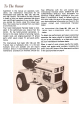
have difficulties with the unit consult your Assembled in this manual are operation, lubriInternational Harvester dealer. UNDER NO CIRcation, and maintenance instructions for the CUMSTANCES SHOULD YOU ATTEMPTTO International Cub Cadet 86, 108, 128, 129, 149, SERVICE THESE UNITS YOURSELF. Only your and 169 Tractors. The material has been prepared dealer is authorized to repair or replace units on in detail to help you better understand the correct this drive under the terms of the warranty.
MODEL DELIVERY DATE Serial No. 500718 and above. A variety of extra equipment and accessories isavailable. LEFT and RIGHT indicate of the tractor when facing Where operating and maintaining instruction is required, it is included in the instruction for seat. Reference to F RaNT of the tractor; to REAR the operating and maintaining the tractor. Disregard the instructions for equipment not on your tractor. the left and right sides forward in the driver's indicates the grille end drawbar end.
This symbol is used to call your attention to instructions concerning your personal safety. Be sure to observe and following these instructions. Disengage power to any attachments and stop engine before leaving operator's seat or making any repairs or adjustments. Use care when pulling loads or using heavy equipment: -A. Use only approved hitch points. B. limit loads to those you can safety control. C. Don't turn too sharp, and use care when backing. D.
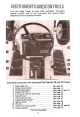
Your Cub Cadet Tractor has been safety engineered. Thoroughly acquaint yourself with all the instruments and controls before attempting to start or operate the tractor. Instruments and controls on the International Cub Cadet 86, 108, and 128 Tractors. 10. 11. 12. 2.4. 3. 5. 6. 7. 8.1. 9. Choke Brake Clutch-brake Creeper Throttle Gearshiftlever Charge Lighting Front Electricliftcontrolswitch* Lift Ignition handle pedal power control indicator shift switch switch camlock take-off pedal lever* button.
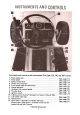
Instruments and controls on the International Cub Cadet 129, 149, and 169 Tractors. 10. 11. 12. 3.9. 4. 7. 8. 2. 1. 5. 6. Speed Choke Charge Throttle Brake Hydraulic Release Lighting Ignition Hour Front Lifthandlecamstop Electrict meter- pedal. power pedal control control indicator lever.switch. 13. lever switch lift* lift lock take-off(Standard control (Not lever button button* shown.
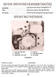
4. Lubrication Lubricate the entire tractor. See pages 33 to 41 Tires. Check the air pressure. See pages 24 to 26 Fuel System. Fill the fuel tank with gasoline. See pages 10 and 11. Fuel line 5. Fuel shut-off valve 6. Air cleaner 1. Fuel tank filler cap 2. Fuel tank 3. Carburetor (not seen) Fuel System. THROTTLE LEVER This lever controls the speed of the engine. When set in a given position, it will maintain a uniform engine speed.
3. 4. 5. 1. 2. OPERATINGTHE ENGINE LIFTING THE HOOD Pull the choke control button all the way out. More or less choking may be necessary due to variations in temperature, grade of fuel, etc. Little or no choking will be needed when the engine iswarm. The tractor hood is arranged to swing up and forward to make the engine and fuel tank readily accessible.
The ~ FUEL SYSTEM This engine is designed to operate on leaded gasoline with a 93 minimum octane rating or on unleaded or low lead gasoline with a 91 minimum octane rating (Research Method). use of unleaded gasoline will lengthen spark plug and valve life, maintain engine performance longer, and reduce rust and corrosion of engine wh ile stored. The fuel tank filler cap has an air vent. Keep the vent open at all times to assure proper flow of thefuel.
11 FUEL SYSTEM CARBURETOR ADJUSTMENTS -Continued A CAUTION! Be sure the brake pedal is in the locked position, transmission is in neutral, and the mower is disenga~d before adjusting the carburetor. If the engine shows a sooty exhaust and is sluggish under load, the high speed mixture is too rich. The high speed adjustment screw must be turned clockwise 1/4 turn at a time until the condition is corrected.
Retighten the cap screws after the seat is adjusted. NOTE: The battery is located in a well under the operator's seat for ease in servicing or replacement when necessary. CLUTCH AND BRAKE PEDAL Brake pedal lock in the engaged position. Adjusting the seat. LOCKING THE BRAKE Always lock the brake when the tractor is parked on a grade. To lock the brake, press down on the pedal; then place the brake pedal lock in the engaged position.
InternationalCub Cadet86, 108 and 128 Tractors CLUTCH-BRAKE free the tractor by speeding up the engine and suddenly engaging the clutch. Try backing out instead of going forward. PEDAL The combination clutch-brake pedal is used to disengage the engine from the transmission when shifting gears and to actuate the brake to stop the tractor. The pedal must be pressed all the way down to activate the safety starting switch when starting the engine. Do not carry passengersor give rides.
1.7 2.5 2. 3. 4. DRIVING THE TRACTDR International Cadet 86, 108 and 128 Tractors OPERATING THE CREEPER DRIVE SPEED TABLE Miles Per Hour Gear Creeper Direct Drive Drive Second 2.3 .6 3.5 1.0 6.8 .6 Reverse International Cub Cadet 129, 149, and 169 Tractors BRAKE PEDAL The brake pedal must be pressed all the way down to activate the safety starting switch. When the brake pedal is in the depressed position it automatically moves the speed control lever to the "N" position.
DRIVING THE TRACTOR International Cub Cadet 129, 149, and 169 Tractors CAUTION! Never operate engine with release lever in (up) position. Towing or pushing the tractor for more than a few 1. Depress the brake pedal and release the brakelock. feet may result in transmission damage. Move the throttle lever to the position wherethe engine operates best for the load to be handled. STOPPING THE TRACTOR 2.
1. Lift lever 2. Draw bar 3. Three-point hitch Orawbar and three-point hitch shown on International Cub Cadet 86 Tractor. DRAWBAR 4. Cam lock knob 5. Cam stop 6. Tang 1. Release button2. Lock button3. Lift handle Orawbar equipment must be hitched to the tractor only at the hitch hole in the drawbar. Adjustable stop limiting handle travel. THREE-POINT HITCH When the tractor has a three-point hitch, equipment adaptable to this hitch is raised and lowered with the lift handle or power lift control.
3. InternationalCub Cadet86, 108and 128 Tractors 1. Shifter lever OPERATING THE REAR POWER TAKE-OFF WITH THE TRACTOR STANDING STILL 1. Move the throttle lever back to the "SLOW" speed. 2. Depress the pedal and move the transmission gearshift lever to the neutral position. 1. Power take-off guard 2. Greasefitting Move the shifter position. lever forward to the engaged If your tractor is equipped with a rear power take-off, the following instructions should be carefully studied and followed. 4.
3. OPERATING THE FRONT POWER TAKE-OFF CLUTCH t. Move the throttle "slow" position. 2. Move the control engaged position. lever back to the medium or lever forward slowly to the Advance throttle to operating speed. ADJUSTING THE POWER TAKE-OFF CLUTCH 1. Clutch lever bracket 2. Quick attachable cotter pin 3. Clutch lever rod 4. Clutch control handle 5. Turnbuckle The clutch is factory adjusted require further adjustment under conditions.
ELECTRIC LIFT OPERATING INSTRUCTIONS 1. Locking knob2. Cam stop3. Rockshaft arm described on page 15 to allow implement to return to a single preset hei~ht. 1. Float lockout pin (optional)2. Electric lift unit 3. Pivot pin To operate equipment in a fixed "locked" position, where down pressure of implement is required (that is blade work); remove frame cover and remove cotter pin in pivot. Reverse lock pin (optional) and insert into pre-aligned holes in clevis and lower portion of rockshaft arm.
1. Float lockout pin (optional)2. Hydrostatic drive unit3. Cotter pin The hydraulic lift engine is running. OPERATING is ready to operate when the 1. Hydraulic lift handle2. Cam stop3. Locking knob INSTRUCTIONS The hydraulic control lever is spring loaded. To raise the equipment move the lever back, toward the tractor seat. To lower the equipment move the lever forward, as shown.
ENGINE COOLING This tractor has an air cooled engine. Air must be able to circulate freely around the engine, through the screen, shroud, and over the fins of the cylinder head and cylinder block. Keep these areas free of accumulated dirt and trash or engine will overheat and result in damaged moving parts. Periodic cleaning with compressed air will keep area clear for adequate cooling. Incoming air for combustion is filtered by a dry-type air cleaner having a filter element inside of the cover.
ELECTRICAL SYSTEM CHARGE INDICATOR Be sure the gasket is in good condition. Tighten the plug 1/2 to 3/4 turns past tiger tight. This instrument indicates whether the motorgenerator is charging or the battery is discharging. If it shows discharge continuously, investigate the cause to avoid completely discharging the battery and possible damage to the motor-generator. Replace a defective plug with a new plug.
ELECTRICAL SYSTEM MOTOR-GENERATOR BELT -Continued Adjusting the Motor-Generator Belt Loosen the motor-generator brace bolt and mounting bolts. Move the generator away from the engine until the tension on the belt is correct. NOTE: Under no circumstances should a pry bar be used on the motor-generator to obtain belt tension as damage to the bearings will result. VOLTAGE REGULATOR A satisfactory generator charging rate is maintained by the voltage regulator.
ELECTRICAL SYSTEM When replacing a battery, make certain the ground cable is connected to the negative (-) terminal on the battery. Be sure the rubber boot is properly positioned over the positive (+) terminal on the battery. NOTE: Both cables must be assembled with the nuts to the inside of the terminals to prevent shorting against fender well. CAUTION! If the rider is to be tipped up or on its side remove the batteries to avoid spilling the electrolyte.
PNEUMATIC CARE OF TIRES TIRES MOUNTING TIRES ON THE RIM Avoid stumps, stones, deep ruts, curbs, and other hazards. Cuts in tires should be repaired immediately as neglect decreases the tire life. After mounting a new or old tire on the rim, inflate it to 20 pounds pressure to seat the tire bead on the rim flange. Then deflate the tire to the correct operating pressure. Keep tires free from oil and grease as both destroyrubber.
FRONT QUICK ATTACHING LATCH This latch is used for front and center mounted equipment. Refer to the equipment manual for proper instructions. FRONT WHEEL TOE-IN Tie rod and drag link ball joints. The front wheel toe-in dimension is approximately 1/8-inch closer in front than in the rear. To measure for proper toe-in, make a chalk mark on the centerline of each tire the same height from the ground as the front wheel hubs.
International Cub Cadet 86, 108 and 128 Tractors Push the pedal down until the clutch just begins to release. This can be checked by shifting the transmission into third gear and rocking the tractor back and forth. If the drive shaft turns free and does not turn the engine, the clutch is disengaged. Locate the pedal at this point with a "c" clamp and adjust the jam nuts on both brake rods until the brakes just begin to clamp the brake discs and create some drag.
CLUTCH-BRAKE ADJUSTING THE BRAKES -Continued To adjust the brakes block the front wheels securely and raise the tractor so the rear wheels are off the ground. A CAUTION! Be careful and take necessary precautions when raising tractor off the ground.
International Cub Cadet129, 149 and 169 Tractors "" """" Speed control handle centering zone when brake pedal is used """ "N" position. Transmissionis in neutral I I Braking zone. Brake must be engaging ~ With pedal lock in position as shown brakes must withstand a torque of 100 ft.lbs. per wheel ,.. (-"-..r-l~ ~...~ ~ Wear zone MA.5151 .:: r)I I I -r::;:::- r-t-.. ../1 -.." J FF L -~ Pedal stop -I -.t1 -- =.==.:1, I' I' "-r"--'-,,; ~ - I I " ~"b-+- :'~=~~::::.:;~-.
8. 9. 4. 6. Cleanthe exterior of the engine. When your tractor is not to be used for some time, it should be stored in a dry and protected place. Leaving your tractor out-doors, exposed to the elements materially shortens its life. 7. Remove the battery and place it in a cool, dry place above (+32°F.). Check battery at leastonce a month for water level and amount of charge. See pages24 and 25. Follow the procedure outlines below when storing a tractor for an extended period of time. 1.
When you purchased your tractor, you probably The tractor is used for so many different types of had it completely equipped for your particular work, and because it is called on to operate under needs at the time. However, later you may wish to so many different conditions, a variety of equipobtain some of the equipment or accessories shownbelow. ment is available to adapt it to the requirements of These items and other allied equipment can the user.
TROUBLE SHOOTING Possible Cause ENGINE Spark Poor Engine or plug incorrectly weak dirty; spark. wrong timed gap or Possible Remedy OPERATES wrong IRREGULARLY OR KNOCKS * type. Clean, reset the gap to .025 inch, or replace. Check the breaker points and breaker point openEngine Enginesmokes Carburetor Poor grade overheating valves fuel setting at or fault water incorrect. ".'..'.'.'..' in ing, spark plug, and wiring.* Adjust; see "Carburetor" on pages 10 and 11.
ENGINE OIL Lubricate the entire tractor, using only high quality lubricating oils and greases as specified in the "Lubrication Table". For your own protection, select only oils and greases of recognized manufac- The engine crankcase is filled with ship-away oil. This oil may be used for the first 30 hours of engine operation at temperatures between +90 degrees F. and 0 degrees F.
lUBRICATION ENGINE OIL -Continued Keep your supply of lubricating oil absolutely clean and free from dust. Always use clean containers. Keep the lubricator clean and wipe dirt from the lubrication fittings before applying the lubricator. TRANSMISSION OIL FILTER (International Cub Cadet 129, 149, and 169 Tractors) Remove the throw-away can-type filter and replace with a new filter after the first 10 hours and after 50 hours of operation, and every 100 hours of operation thereafter. 1.
Check Point of Lubrication at Hours Engine Crankcase Model 86 Tractor 10 Above +32°F. Hours 30 10 30 3 pt. Transmission Models 129,149, and 169 Tractors 100 Add as needed 14pt. Transmission Models 86, 108, and 128 Tractors 100 Add as needed 7 pt. Approx. Creeper drive housing Models 86, 108 and 128 Tractors 100 Add as needed 1/2 pt. Steering knuckles All models +3~F. Yearly 10 to O"F. 2-1/2 pt. I.H. No.
LUBRICATION GUIDE InternationalCub Cadet86, 108and 128 Tractors ~ Q) '; c 0 ';:; ~ '~ ..
LUBRICATION GUIOE InternationalCub Cadets86, 108and 128 Tractors -After 1 -Oil filler cap and bayonet-type oil level gauge. Cub Cadet 86. 1A -Oil filler cap and bayonet-type oil level gauge for Cub Cadet 108 and 128. Check the oil (with the engine stopped) and add sufficient new oil to bring it to the "FU LL" mark on the gauge. Do not overfill. Do not operate the engine if the oil level is below the "LOW" mark on the gauge.
LUBRICATION GUIDE InternationalCub Cadet86, 108and 128 Tractors -Periodic Transmission 6 -Oil 7 -Oil level and filler drain plug. plug. Creeper drive housing 8 -Level plug. 9 -Breather and filler 10 -Drain plug. Check the oil level periodically. Keep the lubricant up the the level plug (6) on the rear of the transmission case. Check the oil level periodically. the level plug (8) on the left Keep the lubricant up to side of the creeper drivehousing plug.
- e ~ ~ e'!' -1 ~ J~-~GI~".-O.~ ~ 0 ~) : .0 ~ ~£~> I , ) """ ~ "; -=QI~ 31~ ~ ". /' :~:r- J'"' Cub Cadet 129, 149, and 169 T LUBRICATION ~ i I I I I II l I '-' I 39 ." ~ ." ~ .( ~ 'S: 0 c ~ ';;' ": ..J ~ .
2. 4. 5. 6. 8. LUBRICATION GUIDE International Cub Cadet 108, 149, and 169 Tractors -After Every 10 Hours of Operation Check the oil (with the engine stopped) and add sufficient new oil to bring it to the "FU LL" mark on the gaugE:.Do not overfill. Do not operate the engine if the oil level is below the "LOW" mark on the gauge. 1. Oil filler cap and bayonet-type oil level gauge. Steeringknuckes (2).3. Front axle pivot pin.
LUBRICATION GUIDE International Cub Cadet129, 149,and 169 Tractors -Periodic Once a year, apply two strokes of the lubricator, using I H 251 H EP grease or equivalent #2 multi-purpose lithium grease. Steering gear housing. NOTE: To locate the lubrication fitting, turn the front wheels to the maximum right turn position. Then reach up under the right side of the tractor frame to locate the fitting. Speed Control Linkage 10. Speed control rod. 11.
SPECIFICATIONS Model 86 ENGINE -Continued Ignition (electric starting) Spark plug gap (14mm plug) (Champion J-8 or equivalent) (Champion H-10 or Battery Voltage Delco- Battery Model 149 Battery Model 169 Battery .025 in. gap .020 in. gap 20 degrees before TOC .025 in. gap .020 in. gap 20 degrees before TOC .025 in. gap .020 in. gap 20 degrees before TOC .025 in. gap .020 in. gap 20 degrees before TOC 12 volt neg. 12 volt neg. 12 volt neg. 12 volt neg. 12 volt neg. 12 volt neg.
MOWERS (38, 44, and 50-inch, 3 spindle) with wide-oval runners and Quick-attachable mounting 45
Your new rotary mower is designed to meet today's exacting operating requirements. The ease of operation and ability to adjust to field conditions lighten your work and shorten your hours on the job. Be sure to read the instructions for Adjusting and Operating in this manual. Check each item referred to and acquaint yourself with the adjustments required to obtain efficient operation and maximum trouble-free performance.
ute The 3 spindle, center mounted, 38-, 44-, and 50inch rotary mowers are designed for use on International Cub Cadet Tractors having serial number 400,001 and higher, and are quick detachable by the use of two spring loaded handles and two bayonet type hangers. The three cutting blades are designed to create a suction to lift the grass and hold it for an even cut. Raising and lowering of the mower is done by means of the tractor lift handle or the power lift.
Do 2. 3. 4. CAUTIONI This symbol is used to call your attention to instructions concerning your personal safety. Be sure to observeand follow these precautionary instructions. Be sure all stones, branches, or other objects that might be picked up and thrown by the mower blades are removed before starting to mow. The discharge shield on the mower must be attached at all times while operating the mower. Keep the machine in good operating condition and keep safety devices in place.
1. 2. 3. 4. 5. 6. 7. 8. Power take-off clutch lever Mower support brackets Mower support clevises Runners Lift stop Hydraulic lift handle V-belt tension bolt Extension spring measurement 9. 10. 11. 12. 13. 14. 15. 38-inch mower.
~D OPERATING 8. Idler spring tension release 9. Quick hitch10. Power take-off clutch rod 11. Support pins (spring loaded) 12. Deflector shield13. Gauge wheels 1. Power take-off clutch lever2. Mower support brackets3. Mower support clevises4. Runners5. Lift stop6. Electric lift control switch*7. V -belt tension bolt 44 and 50-inch mower.
51 ADJUSTINGAND OPERATING LEVEL ADJUSTMENT -Continued 1. Support brackets2. Support clevises 38-inch mower shown. A CAUTION! Be sure to turn off the engine, remove the ignition key, set the brake pedal in the locked position, and disengagethe power take-off clutch. Set the lift handle stop for the desired mowing height. To set the lift handle stop, raise the mower to the desired cutting height and adjust the stop so it contacts the lift handle. Then tighten the knob securely.
ADJUSTINGAND OPERATING V-BEL T Main Drive Belt-(38-inch mower) 1. V-belt tension bolt2. Extension spring measurement3. Front hanger cover The main drive V -belt is adjusted for tension by the V-belt tension bolt. Tighten the locknut to increase belt tension and loosen the locknut to decrease the belt tension. When belt slippage occurs or spring coils touch, readjust to 1/16-inch spread. Under no condition should the tension adjustment distance be allowed to fall under 3-1/8-inches.
AND OPERATING V-BEL T Main Drive Belt-(44-inch and 50-inch mowers) 1. Front cover2. Idler ratchet3. V -belt tension bolt main drive V-belt is properly tensioned whenthe NOTE: When installing new belt always check idler ratchet is positioned as shown on the the condition of the pull! ~ys and if they are not inreplace decal on the front cover of the lift frame. them with newr satisfactory condition, I pulleys dealer.
ADJUSTINGAND DPERATING HEIGHT OF CUT Also, before winter storage, remove idler pivot shaft and grease the area where the torsion spring and id ler arm tube ride. Set the lift stop for the desired height of cut. Refer to the Tractor Operator's Manual with respect to the type of I ift system on the tractor. CLEANING Clean the underside of the mower at the end of the mowing season and when the build-up of cut material on the underside is noticed. Also, remove the belt cover and remove any accumulation.
No accident-prevention program can be suc- industrial plant, can be safer than the man who cessful without the wholehearted co-operation is at the controls. of the person who is directly responsible for the vented-and operation of equipment. done by the operators who accept a full measure To read accident reports from all over the If accidents are to be pre- they can be prevented-it will be of their responsibility.