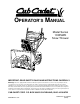
OPERATOR’S MANUAL Model Series 1333SWE Snow Thrower IMPORTANT: READ SAFETY RULES AND INSTRUCTIONS CAREFULLY Warning: This unit is equipped with an internal combustion engine and should not be used on or near any unimproved forestcovered, brush-covered or grass-covered land unless the engine’s exhaust system is equipped with a spark arrester meeting applicable local or state laws (if any). If a spark arrester is used, it should be maintained in effective working order by the operator.
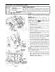
SECTION 1: FINDING YOUR MODEL NUMBER This Operator’s Manual is an important part of your new snow thrower. It will help you assemble, prepare and maintain your snow thrower. Please read and understand what it says. Before you start to prepare your snow thrower for its first use, please locate the model plate and copy the information from it in this Operator’s Manual. The information on the model plate is very important if you need help from your dealer. • Every snow thrower has a model plate.
SECTION 3: IMPORTANT SAFE OPERATION PRACTICES WARNING: THIS SYMBOL POINTS OUT IMPORTANT SAFETY INSTRUCTIONS WHICH, IF NOT FOLLOWED, COULD ENDANGER THE PERSONAL SAFETY AND/OR PROPERTY OF YOURSELF AND OTHERS. READ AND FOLLOW ALL INSTRUCTIONS IN THIS MANUAL BEFORE ATTEMPTING TO OPERATE YOUR SNOW THROWER. FAILURE TO COMPLY WITH THESE INSTRUCTIONS MAY RESULT IN PERSONAL INJURY. WHEN YOU SEE THIS SYMBOLHEED ITS WARNING.
• If the snow thrower should start to vibrate abnormally, stop the engine and check immediately for the cause. Vibration is generally a warning of trouble. • Never operate the machine at high transport speeds on slippery surfaces. Look behind and use care when backing. • Never direct discharge at bystanders or allow anyone in front of unit.
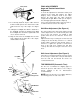
SECTION 4: SET-UP INSTRUCTIONS Shear Bolts 5/16-18 x 1-1/2" Long (710-0890A) Hex Lock Nuts 5/16-18 Thread (712-0429) AUGER SHEAR BOLTS The augers are secured to the auger shaft with two shear bolts and hex lock nuts. If you hit a foreign object or ice jam, the snow thrower is designed so that the bolts will shear. Two replacement shear bolts and nuts are provided for your convenience.
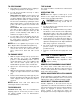
FINAL ADJUSTMENTS Auger and Traction Control Clutch Adjustment Cable Guide To check the adjustment of either drive clutch, push forward on the clutch grip (depress the rubber bumper). There should be slack in the cable. Release the clutch grip. The cable should be straight, but not tight. Make certain you can depress the clutch grip against the handle completely. Figure 6 If necessary, thread lock-nut up to increase tension or down to decrease tension. See Figure 7. 11.
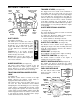
SECTION 5: CONTROLS Auger Drive Clutch Chute Tilt Control Left Trigger Lever TRIGGER LEVERS (See Figure 10) Traction Control/ Auger Clutch Lock The trigger levers are located on the underside of the handles and are used to help you steer your snow thrower. To turn right, squeeze the right trigger lever and guide the snow thrower to the right. To turn left, squeeze the left trigger lever and guide the snow thrower to the left.
SECTION 6: OPERATION NOTE: This unit has been shipped with oil in the Metal Loop on Spark Plug Wire engine. Check oil before starting engine. GAS AND OIL FILL-UP Check oil level and add oil if necessary. Service the engine with gasoline as instructed in the separate engine manual packed with your snow thrower. Read instructions carefully. Rubber Boot Figure 13 ENGINE WILL NOT START UNLESS IGNITION KEY IS INSERTED INTO IGNITION SLOT IN CARBURETOR COVER. DO NOT TURN IGNITION KEY.
TO STOP ENGINE TIRE CHAINS 1. Run engine for a few minutes before stopping to help dry off any moisture on the engine. Tire chains should be used whenever extra traction is needed. 2. To help prevent possible freeze-up of starter, proceed as follows: Optional Electric Starter Connect power cord to switch box on engine, then to 120 volt AC receptacle. With the engine running, push starter button and spin the starter for several seconds.
SHIFT ROD ADJUSTMENT CARBURETOR ADJUSTMENT To adjust the shift rod, remove the cotter pin which secures the shift rod to the shift lever. For proper adjustment, refer to FINAL ADJUSTMENTS on page 6. WARNING: If any adjustments are made to the engine while the engine is running (e.g. carburetor), keep clear of all moving parts. Be careful of heated surfaces and mufflers.
SECTION 9: MAINTENANCE WARNING: Disconnect the spark plug BELT REMOVAL AND REPLACEMENT wire and ground against the engine before performing any repairs or maintenance. WARNING: Remove the spark plug wire from the spark plug and ground. Drain gasoline from the fuel tank, or place a piece of plastic film underneath the gas cap to prevent gasoline from leaking. AUGERS The augers are secured to the spiral shaft with two shear bolts and hex lock nuts. See Figure 16.
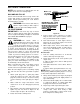
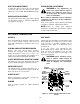
Engine Pulley Brake Bracket Assembly Large Shoulder Bolt Auger Control Belt Pulley Extension Spring Figure 18 Auger Idler Rod Belt Keepers Ferrule Brake Bracket Assembly Proper Adjustment With the auger clutch lever in the disengaged position the top surface of the new belt should be even with the outside diameter of the pulley. To adjust, disconnect ferrule from the brake bracket assembly and thread ferrule in (towards idler) to increase tension on belt, out to decrease tension.
Changing the Friction Wheel The rubber on the friction wheel is subject to wear and should be checked after 25 hours of operation, and periodically thereafter. Replace the friction wheel rubber if signs of excessive wear or cracking are found. Sprocket Shift Rod Assembly Pin Friction Wheel Assembly Spacer 1. Drain the gasoline from the snow thrower, or place a piece of plastic under the gas cap. Support Bracket 2. Tip the snow thrower up and forward, so that it rests on the housing. Shaft 3.
SECTION 11: TROUBLE SHOOTING GUIDE Trouble Possible Cause(s) Corrective Action Engine fails to start Fuel tank empty, or stale fuel. Fill tank with clean, fresh gasoline. Fuel will not last over thirty days unless a fuel stabilizer is used. Blocked fuel line. Clean fuel line. Choke not in ON position Move switch to ON position Faulty spark plug. Clean, adjust gap or replace. Key not in switch on engine. Insert key. Spark plug wire Connect spark plug wire. disconnected. Primer button not depressed.
SECTION 12: Illustrated Parts Model 1333SWE Ref. No. 1 2 3 4 6 7 8 9 10 11 12 Part No. 731-1364 710-1240 712-0271 725-1669 629-0059 725-1658 710-0451 710-1003 736-0159 712-0429 731-0061 735-0225 705-5217 Description Halogen Lamp Housing Phillips Pan Head Screw M 4 x 16 Hex Sems Nut 1/4-20 Lamp/Lens Housing Ass’y Halogen Light Wire Harness #890 Halogen Bulb Carriage Bolt 5/16-18 x .75 Pan Head B-Tapp Screw #10 Fl-Wash .344 ID x .88 OD Hex Ins L-Nut 5/16-18 Handle Panel Grommet .38 ID x .
Model 1333SWE 2 7 64 82 72 77 12 8 20 18 13 11 10 75 5 17 15 14 8 16 9 27 27 8 19 6 3 75 13 12 1 7 4 26 27 83 66 82 83 23 85 22 25 7 12 72 21 24 84 11 64 78 65 27 66 85 79 12 71 80 68 84 86 68 76 56 68 53 71 81 63 67 69 1 62 37 69 47 63 70 68 74 44 48 49 39 44 48 43 34 43 50 49 45 39 35 42 52 73 39 40 61 59 75 51 48 62 41 36 41 60 37 16 55 57 58 54
Model 1333SWE Ref. No. 1 2 3 4 5 6 7 8 9 10 11 12 13 14 15 16 17 18 19 20 21 22 23 24 25 26 27 34 35 36 37 39 40 41 42 43 44 45 47 Part No.
Model 1333SWE 8 18
Model 1333SWE Ref. No. 1 2 4 6 8 15 16 17 19 20 23 Part No.
Model 1333SWE 6 14 10 14 6 4 13 3 21 17 13 7 20 12 16 1 11 9 12 2 8 3 5 5 18 19 22 24 23 20
Model 1333SWE Ref. No. 1 2 3 4 5 6 7 8 9 10 11 12 Part No. 07386 684-0123A 710-0191 710-0237 710-0502A 710-0607 710-1245 712-0116 714-0118 731-0321 732-0303 736-0217 Description Wash:.390 ID x 1.75 O.D. Brkt Asm:Cvr:Belt Hex Hd. Screw 3/8-24 x 1.25 (Gr. 8) Hex Hd. Screw 5/16-4 x .625 (Gr.5) Hex TT-Sems Screw 3/8-16 x 1.25 Hex TT-Tap Screw 5/16-18 Thd. Hex Lock Screw 5/16-24 x .875 Jam Nut 3/8-24 Thd. Key Cvr:Belt Spring:Extension L-Wash .3/8 Qty. 1 1 2 3 4 3 1 1 1 1 1 2 Ref. No.
Model 1333SWE 22 65 12 8 22 20 73 76 9 80 78 51 82 81 55 45 17 22 11 19 63 68 38 26 49 54 39 49 62 38 10 49 4 38 46 34 35 23 53 27 5 47 24 49 36 68 3 57 46 25 42 18 24 37 36 66 61 53 69 75 19 15 50 33 6 41 71 56 63 16 14 1 28 80 16 72 64 59 58 32 50 2 43 32 19 13 7 17 28 50 47 70 62 56 53 67 34 57 61 60 47 53 33 48 29 51 54 23 52 34 40 74 22 22 22 78
Model 1333SWE Ref. No. 1 2 3 4 5 6 7 8 9 10 11 12 13 14 15 16 17 18 19 20 22 23 24 25 26 27 28 29 32 33 34 35 36 37 38 39 40 41 42 Part No.
MANUFACTURER’S LIMITED WARRANTY FOR: TWO-YEAR RESIDENTIAL ONE-YEAR COMMERCIAL Proper maintenance of your Cub Cadet equipment is the owner’s responsibility. Follow the instructions in your operator’s manual for correct lubricants and maintenance schedule. Your Cub Cadet dealer carries a complete line of quality lubricants and filters for your equipment’s engine, transmission, chassis and attachments.