OPERATOR'S MANUAL © i ,_% qlL ' J_, I r_ g'?A'_-f-I ,':,:,=" ____--c;-- @ i i t ',, r@ /I IP' , / t TRACTORS Model Numbers RZT 50 RZT 54 IMPORTANT: READ SAFETY (w/50" Mower Deck) (w/54" Mower Deck) RULES AND INSTRUCTIONS CAREFULLY Warning: This unit is equipped with an internal combustion engine and should not be used on or near any unimproved forestcovered, brush-covered or grass-covered land unless the engine's exhaust system is equipped with a spark arrester meeting apphcable lo
TABLE OF CONTENTS TRACTOR PREPARATION .................................................................................................... IMPORTANT SAFE OPERATION PRACTICES .................................................................... SAFETY DECALS AND LABELS ........................................................................................... SLOPE GAUGE ...................................................................................................................... TO THE OWNER ........
POSITION DRIVE CONTROL LEVERS CONNECT THE BATTERY The drive control levers of the tractor are lowered for shipping purposes. To accomplish this, the flange lock nut, hex screw, and flat washer normally used to secure each control lever to its pivot bracket are removed. The hardware is then installed in the slotted hole of each control lever for shipment. The control levers must be moved to their operating position.
WARNING • The engine exhaust, some of its constituents, and certain vehicle components contain or emit chemicals known to the State of California to cause cancer, birth defects or other reproductive harm. • This unit is equipped with an internal combustion engine and should not be used on or near any unimproved forest-covered, brush-covered, or grass-covered land unless the engine's exhaust system is equipped with a spark arrester meeting applicable local or state laws (if any).
13.Mowonlyin daylightor goodartificiallight. 14.Do not operatethe machinewhile under the influenceofalcoholor drugs. 15.Watchfortrafficwhenoperatingnearor crossing roadways. 16.Use extra carewhen loadingor unloadingthe machineintoa trailerortruck.Thisunitshouldnot bedrivenupor downa rampontoa trailerortruck under power,becausethe unit could tip over causingseriouspersonalinjury.Theunitmustbe pushedmanuallyon a rampto load or unload properly. 17.
5. Never allow children under 14 years old to operatethe machine.Children14yearsandover shouldonly operatethe machineunderclose parentalsupervision andproperinstruction. 6. Useextracarewhenapproaching blindcorners, shrubs,treesor otherobjectsthatmayobscure yourvisionof a childor otherhazard. 7. Removethe key when the machineis left unattended to preventunauthorized operation. ,_ IV. SERVICE , Use extreme care in handling gasoline and other fuels. They are extremely flammable and the vapors are explosive.
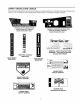
SAFETY DECALS AND LABELS Keep product safety graphics (decals) clean. Replace any safety graphic that is damaged, destroyed, missing, painted over or can no longer be read. Replacement safety graphics are available through your dealer. GENERAL SAFETY INSTRUCTIONS - LOCATED ON LEFT CONSOLE ASIDE OPERATOR'S SEAT GENERAL OPERATING INSTRUCTIONS - LOCATED ON RIGHT CONSOLE ASIDE OPERATOR'S SEAT Time S r I xJ.
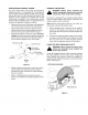
USE THIS PAGE AS A GUIDE TO DETERMINE SLOPES WHERE YOU MAY NOT OPERATE SAFELY. I • ql ! SIGHT AND HOLD THIS LEVEL WITH A VERTICAL TREE I_ I I I A POWER POLE I _1 A CORNER OF A BUILDING OR A FENCE POST ! "O t,n 5" ='0 EITI oo o I E 15° ,L.., ,_ WARNING Do not mow on inclines with a slope in excess of 15 degrees (a rise of approximately 2-1/2 feet every 10 feet). A riding mower could overturn and cause serious injury.
TO THE OWNER This Operator's Manual is an important part of your new tractor. The information contained in this manual has been prepared in detail to help you better understand the features, correct operation, adjustments, and maintenance of your tractor. The performance and dependability of this tractor rely greatly on the manner in which it is operated and maintained. Therefore, it is recommended that all operators of the tractor carefully read this manual and fully understand its operation.
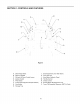
SECTION 1" CONTROLS AND FEATURES o K 'i Figure 5 A. Deck Height Index B. Deck Lift Handle C. RH and LH Drive Control Levers J. Seat Adjustment Lever (Not Seen) K. Fuel Tank Cap L. Hour Meter/Indicator Panel D. Ignition Switch E. PTO Switch M. Throttle Control N. Choke Control F. Transmission G. Cup Holder Bypass Rod (Not Shown) O. Parking Brake Engagement Lever P. Trans. Oil Expansion Reservoir (RZT 54 Only) H.
NOTE: References to LEFT, RIGHT, FRONT, and REAR indicate that position on the tractor when facing forward while seated in the operator's seat. A. E. Power Take-Off (PTO) Switch The PTO switch is located on the RH console to the right of the operator's seat. Deck Height Index The deck height index consists of six index notches located on the front/right of the seat box frame.
WARNING: Never fill the fuel tank when the engine is running. If the engine is hot from recently running, allow to cool for several minutes before refueling. Highly flammable gasoline could splash onto the engine and cause a fire. L. Hour Meter/Indicator check the battery and charging system for possible causes and/or contact your Cub Cadet dealer. Oil Pressure Indicator • Panel The hour meter/indicator panel is located on the LH console to the left of the operator's seat.
N. ChokeControl Thechokeknobcontrolsthepositionoftheengine choke.Pulltheknobouttochoketheengine;pushthe knobintoopenthechoke. P. MODEL RZT 54 ONLY - Transmission Oil Expansion Reservoir The transmission oil expansion reservoir is connected by hoses to the RH and LH transmission assemblies, and is located beneath the seat box. The function of the reservoir is to hold the natural expansion of transmission oil that occurs as the transmission warms up during operation. DO NOT FILL THE RESERVOIR. O.
• Thisengineis certifiedto operateonlyon clean, fresh,unleadedregulargasoline.Forbestresults, fill the fueltank withonlyclean,fresh,unleaded gasolinewitha pumpstickeroctaneratingof 87 or higher. • Unleadedgasolineis recommended becauseit leavesless combustionchamberdepositsand reduces harmful exhaust emissions.Leaded gasolineis not recommended and mustnot be usedwhereexhaustemissions areregulated. NOTE:Purchase gasoline in small quantities.
enginedoesnotstartwithinthistime,turnthekey to"OFF"andwaitatleast15secondsto allowthe engine'sstartermotorto cool. Try againafter waiting.If aftera few attemptsthe enginefailsto start,do notkeeptryingto startit withthe choke closedasthis willcausefloodingandmakestartingmoredifficult. As the enginewarmsup, graduallypush the chokeknobdownward to openthe choke.Donot usethe choketo enrichthe fuelmixture,except as necessary to starttheengine.
• • Adjust the operator's seat to the most comfortablepositionthat allowsyou to operate the controls. See seat adjustment in the ADJUSTMENTS section. Releasetheparkingbrake. Movethe RHandLHdrivecontrolleversinward inthe neutralposition.Referto Figure11. • As the control levers are pushed farther forward the speed of the tractor will increase.
Toturntothe right,movetherightdrivecontrol leverrearward ofthe leftlever.SeeFigure14. IMPORTANT: Always maintain your grasp on the drive control levers. Do not release the levers to slow the tractor or to return to neutral. FORWARD RIGHT TURN Turning While Driving Rearward • To turn the tractor while driving rearward, move the control levers as necessary so that one lever is forward of the other. The tractor will turn in the direction of the forward control lever.
STOPPING THE TRACTOR Executing a Zero Turn _ the tractor MUST BE STOPPED. WARNING: When executing a zero turn, Executing a zero turn while the tractor is moving can significantly reduce your control of the tractor and will cause severe turf defacement to occur. • Stop the forward or reverse motion of the tractor by moving the two drive control levers to neutral. • To turn clockwise, move the left control lever forward while simultaneously moving the right control lever rearward. See Figure 18.
USING THE MOWER DECK IMPORTANT: When stopping the tractor reason while on a grass surface, always: WARNING: Make certain the area to be mowed is free of debris, sticks, stones, wire or other objects that can be thrown by the rotating blades. • • • Mow across slopes, not up and down. If mowing a slope, start at bottom and work upward to ensure turns are made uphill. • On the first pass pick a point on the opposite side of the area to be mowed.
SECTION 3: ADJUSTMENTS ADJUSTING THE OPERATORS SEAT To adjust the position of the seat, move and hold the seat adjustment lever toward the left. Slide the seat forward or rearward to the desired position; then release the adjustment lever. Make sure seat is locked into position before operating the tractor. See Figure 20. • Reposition the control lever to align with the other set of holes in the pivot bracket and insert the shoulder screw removed earlier.
SECTION 4: MAINTENANCE ENGINE MAINTENANCE Model RZT 54 ONLY Engine maintenance procedures and schedules can be found in the copy of the engine manual found at the end of this manual. Follow those schedules for performing engine maintenance. The model RZT54 is equipped with a transmission oil expansion reservoir. Under normal operating conditions, the oil level in the expansion reservoir does not need to be checked and no additional oil is needed.
• • • Keepall sourcesof ignition(cigarettes, matches, lighters)awayfromthe battery.The gas generatedduringchargingcanbecombustible. Asa furtherprecaution, onlychargethebatteryin a wellventilatedarea. Alwaysshieldeyesandprotectskinandclothing whenworkingnearbatteries. CHARGING • BATTERY REMOVAL related accessories contain lead and lead WARNING: Battery posts, terminals and compounds. Wash hands after handling. ,_ State of Charge 100% 75% 50% 25% Charging Time Full Charge 90 Min. 180 Min. 280 Min.
If you havea recurringproblemwith blownfuses, havethe tractor'selectricalsystemcheckedby your CubCadetdealer. RelaysandSwitches Thereare severalsafetyswitchesin the electrical system.If a functionof the safetyinterlocksystem describedearlieris notfunctioning properly,havethe electricalsystemcheckedbyyourCubCadetdealer. • Pull one rod toward the front of the tractor until the flange on the rod is forward of the keyhole slot in the frame assembly.
• • • If the rotationstops,adjusttheferruleupor down thecontrolrodas necessary to alignwiththe hole in the transmissioncontrolarm. Re-insertthe ferruleintothe holeinthecontrolarmandsecure withtheinternalcotterpin. If necessary,repeatthe previoustwo stepsto adjusttheothertransmission controlrod. Lowerthetractorandremovethejack. • Tighten the jam nut against the console and reposition the control lever if necessary.
TRACTORSTORAGE If your tractoris not goingto be operatedfor an extendedperiodof time(thirtydaysto approximately six months),the tractorshouldbe preparedfor storage.Storethe tractorin a dryandprotectedlocation. If storedoutside,coverthetractor(including thetires) to protectit fromthe elements.The procedures outlinedbelowshouldbeperformed whenever thetractor is placedin storage. 1. Changethe engineoil and filter followingthe instructionsprovided in the engine manual packedwiththismanual.
SECTION 5: MOWER DECK This section contains removal, installation, adjustment, and maintenance information for the mower deck. Some of the following information applies only to the model RZT50 deck, while some applies only to the RZT54. Information that applies only to a specific deck model will be preceded by a bold title line that identifies which deck is the subject of that information. Rolling the belt off the PTO pulley.
, Using care to prevent the front hanger rod from falling back into the deck bracket slots, carefully slide the cutting deck (from the right side) out from underneath the tractor. DECK INSTALLATION • Install the belt in the PTO pulley on the bottom of the engine. • Route the backside of the belt around the fixed idler pulley of the deck. Refer to Figure 30.
LEVELINGTHEMOWERDECK Whencorrectlyadjustedthe mowerdeckshouldbe levelsideto side,andthefrontof thedeckshouldbe approximately 1/4inchlowerthantherearofdeck. Sideto SideLeveling If the cuttingdeckappearsto bemowingunevenly,a sideto sideadjustmentcan be performed.Adjustif necessary asfollows: • Withthe tractorparkedon a firm,levelsurface, placethedecklifthandleinthetop notch(highest position)androtatebothouterbladessothatthey areperpendicular tothetractorframe. • Lowerthedecktothe middleheightposition.
ADJUSTING THE GAUGE WHEELS AND ROLLERS Using the lift handle, set the deck in the desired height setting, then check the gauge wheel distance from the ground below. If necessary adjust the front gauge wheels as follows: from the discharge the WARNING: Keep handsopening and feetof away cutting deck. Model RZT50 Gauge Wheels • Visually gauge wheels should ground, • Remove the lock nut securing one of the front gauge wheel shoulder screws to the deck. Remove the gauge wheel and shoulder screw.
DECK MAINTENANCE deck, be careful to cut yourself on the I_WARNING: Whennotservicing the mower sharpened blades. Using the Deck Wash System WARNING: When using the deck wash system, never engage the deck from any position other than the operator's seat of the tractor. Do not use an assistant or engage deck in the presence of any bystanders. • • • The cutting blades must be kept sharp at all times.
REPLACING THE DECK DRIVE BELT Install the new belt around the spindle pulleys as shown in Figure 39 and reinstall the belt covers. Remove the deck from beneath the tractor, (refer to Deck Removal on page 26). Route the belt rearward between the two idler pulleys and reinstall the deck following the instructions in Deck Installation on page 27. Remove the hex tapping screws securing the belt covers to the deck and remove the belt from the spindle pulleys. Refer to Figure 39.
ENGINE MANUAL A Kawasaki engine is used on this RZT tractor model. The following section is a reproduction of the Kawasaki engine manual that applies to the RZT50 and RZT54 engines. The RZT50 use the model FH661, and the RZT54 uses the model FH721V engine. Read this manual in its entirety. Observe all warnings and follow all applicable operation and maintenance instructions provided in the manual.
READ THIS FIRST For your safety, read this Owner's Manual and understand it thoroughly before operating this ENGINE. DO NOT run the engine in a closed area. Exhaust gas contains carbon monoxide, an odorless and deadly poison. Gasollne is extremely flammable and can be explosive under certain condition. Stop engine and allow the engine to cool before refueling. DO NOT smoke.
Engine Emission Compliance Period California All Other States Engines Greater Than 225 cc Engines Greater Than 225 cc Modei Year - 2006 and later Durability period- 500 hours Model Year -2001 Durabili_ and later Period - 1;000 hours (Category A) * If your engine has an assigned emissions durability period it will be located on the ce_ification a_ched to the engine (IMPORTANT ENGINE INFORMATION), label High Altitude Performance Adjustment Information To improve the EMISSIONS CONTROL PERFORMANCE of
VVe wish to thank you for purchasing this Kawasaki engine. Please read this Owner's Manual carefully before starting your new engine so that you will be thoroughly familiar with the proof operation of your engine's control, its features, capabilities and limitations. Also read the manual of the equipment to which this engine is a_ached. To ensure a long, trouble-free life for your engine, give it the proper care and maintenance described in this manual.
8 GENERAL INFORMATION GENE L INFORMATION Location of Safety Related Labels MAINTENANC ENG+NE ++OH+ECK OIL LEVEL 2+¢H+ECK & CLEA_ AiR ¢LEAHER 3._LEAN SCREE# & FtH$ 4. CH;k_GE 0]L & 0+L F+LTE_ A. Warning B+Engine Maintenance REFE_ TO HNER'$ i+AiUALFOR FURTHER iNF_RM_TIOW GENERAL INFORMATION 9 Location of Parts VIEW a FH841 ?04M _' IG I. Electric Starter J. Voltage Regulator A+Oil GaugsdFlller B+Oil Filter C. Oil Drain Plugs D. Air CleanertCarburetor E. Control Panel F.
10 GENERAL INFORMATION Engine Serial Number Tune-up The engine serial number is your only means of identi_ing your particular engine from others of the same model type. This engine serial number is needed by your dealer when ordering parts. Specifications ITEM Specifications Ignffion Timing Unadiustabte Spark Plugs: Gap NGK BPR4ES &75 turn (0.030 in) Low Idle Speed 1 550 r/min (rpm) High Idle Speed _3 600 r/min (rpm) ..... IN 0.10~ 0.15 mm Valve Clearance (0,004 _- &006 in) EX 0.10 _, 0.
12 FUEL AND OIL RECOMMENDATIONS FUEL AND OIL RECOMMENDATIONS ETHANOL: (Ethyl or GrainAlcohol) You may use gasoline containing up to 10% ethanol by volume. MTBE: (Methyl Tertiary ButylEther) You may usegasolinecontainingupto 15% MTBE by volume. METHANOL: (Methylor Wood Alcohol) You may use gasoline containing up to 5% methanol by volume, as long as it also contains cosolventsand corms,ion inhibitorsto protectthe fuel system.
14 PREPARATION PREPARATION • Level the engine before fueling. • Remove the fuel tank cap. • Slowly pour fuel into the tank through the fuel strainer. • Close the tank cap securely. Fuel Gasoline is extremely flammable and can be explosive under certain conditions. Before refueling, turn the engine switch to the OFF position. Do not smoke. Make sure the area is wel| ventilated and free from any source of flame or sparks, including any appliances with a pilot light.
16 STARTING STARTING Use fresh gasohne o Protect the engine or the equipment from direct exposure to weather when not in operation. O Before starting the engine, disconnect all possible external loads. • Open the fuel valve (A) on the equipment. • Put the engine switch key into the engine switch, For Control Panel Switch Type, move the throttle lever on the equipment to its halfway position Moving the lever away from its low speed end turns ignition on.
18 STARTING • Put the switch key (A) into the engine switch. • Turn the switch key to the START position on the equipment. Normally the engine will start within 3 seconds. Do not run the electric starter continuously for more than 5 seconds, otherwise the battery may discharge quickly. If the engine does not start right away, wait 15 seconds and try again. Whenever you start engine, make sure warning light is not illuminated after engine starts.
20 OPERATING Engine Inclination This engine will operatecontinuouslyat anglesup to 25 ° in any direction. Refer to the operating instmc'donsof the equipment this engine powers. Because of equipment design or application,there may be more stringent restdcUonsregardingthe angle of operation. CAUTION Do not operate this engine continuously at angles exceeding 25Q in any direction. Engine damage could result front insufficient lubrication.
22 ADJUSTMENT ADJUSTMENT Two types of choke control are used for FH601V, FH641V, FH661V, FH661V, FH680V, FH721VModel Engines. Associated Choke the lever (C); insert 6 mm dia, pin (or 6 mm bolt) through two hole& • Turn the choke setting screw (I) so that the clearance between the screw end and the tongue of the lever (J) is zero. Remove the 6 mm alia, pin or bolt. • Make sure that the choke valve can move to full open position and fuli c_ose position by turning the lever.
24 ADJUSTMENT Separate • Move the equipmentchoke controlto "CHOKE" Make sure that the carburetor choke valve (M) is completely closed. • Make sure that the choke valve _ms from fully closed positionto fully opened positionwhen actuatingMe equipment choke control. choke type Throttle Cable Installation, Adjustment • Link the throttle cable (G) to the speed control lever (C) and loosely clamp the throttle cable outer housing (F)with the cable clamp bolt (A). • Move the throttle lever to =FAST" position.
26 ADJUSTMENT Engine Speed Adjustment NOTE 0 Do not tamper with the govemorsettfng orthe carburetor setting orthe carburetor settingto increase the engine speed. Every carburetoris adjusted at the factory and a cap or a stop plate was installed on each mixturescrew. 0/f adjustmentis needed, it must be performedby your authorized KawasakiEngine dealer. MAINTENANCE 27 Periodic Maintenance Chart NOTE 0 The set€ice intervals can be used as a guide.
28 MAINTENANCE INTERVAL First Evew Daily 8 hr. 25 hr. MAINTENANCE • Check or dean air inlet screen. Eve_ Every Every Every Evew Every 50 hr. t00 hr. 200 hr. 250 hr. 300 hr. 500 hr. • _Clean dust and dirt: from cylinder Kand cylinder head fins. • Tighten nuts and screws. Change engine oil. • • • _Check and clean oil cooler fins (FH721V model). • Clean and regap spark plugs.
30 MAINTENANCE • _nstall the oil drain p_ug, • Remove the oHgauge and refill with fresh oH (See FUEL AND OIL RECOMMENDATIONS chapter)_ • Check the oil level (see PREPARATION chapter)_ Oil Change Change oil after first 8 hours of operation, Thereafter change oil = Run the engine to warm o& • Be sure the engine (equipment) is on level surface_ • Stop the engine • Remove the oil drain plug and drain the oH into a suitable container while engine is warm. Engine oil is a toxic substance.
32 MAINTENANCE Air Cleaner Service Paper Element Clean the paper etement (B) ...eye.._100 hour& • Clean the element by tapping gently to remove dust. if very di_, replace the e_ement with a new Do not run the engine with the air cleaner removed. one, • Rep!ace w{th a new paper element yearly or 200 hours_ whichever comes first. Foam Element Clean the foam element (A) every, .....
34 MAINTENANCE Cooling System Cleaning Before each 9pe[at!gn, check that the air inlet (retaw) screen (A) is free from grass and debris. Clean, the screen if necessary: Eve_ 100 hours of operation, check and clean the cooling fins and the inside of engine shrouds to remove grass, chaff or di_ clogging the cooling system and causing overheating. When c{eaning, remove the air in_etscreen (A), the air c_eaner cap (C) and the fan housing (B).
36 STORAGE • Remove the spark plugs and pour approx i ~ 2 mL (006 ~ 0_1 cu in) of engine oil through the spark plug holes then screw the spark plugs in after turning the engine a few times. Slowly turn the engine until you feel the compression then leave it there. This traps the air inside the cytinde_ and prevents rust inside the engine • Wipe the body with oily cloth. • Wrap the engine with plastic sheeting and store it in a dry place. • Change engine oil for next use after period of storage.
38 TROOUBLESHOOTING GUIDE Symptom Probable Cause No spark or Faulty spark plugs Repla_ weak spark Low output Remedy spark plugs .......................................................... K .............................................................................
40 WIRING DIAG_M WIRING DiAG_M //_ /J////f////////////////////, (With 12 V - 13 A For electrical safety, always remove cable from negative (-) side of battery before attempting any repair or maintenance. Battery Capacity Q Recommended __ ILawn Mowe[ _--_erj 112 V Capacity [Snow Thio i12v 28O CCAClass lass //._/, /J//./_ NOTE 0 Portion surrounded procurement parts. C. Cha_ing Kawasaki Coil Coil L Voltage Regulator J. Electric Starter D. Spark Plugs K.
KAWASAKI LIMITED WARRANTY CALIFORNIA AND FEDERAL EMISSIONS CONTROL SYSTEMS SMALL OFF-ROAD ENGINES The California Air Resources Board, the Environmental Protection Agency (EPA) , and Kawasaki Motors Corp., U.S.A. (hereinafter "Kawasaki") are pleased to explain the Emission Control Systems Warranty on your Kawasaki small off-road engine. In California and other states, new small off-road engines must be designed, built and equipped to meet the stringent anti-smog standards.
3. LIMITED LIABILITY. (a) The liability of Kawasaki under this Emission Control Systems Warranty is limited solely to the remedying of defects in materials or workmanship by any authorized Kawasaki small off-road engine dealer at its place of business during customary business hours. This warranty does not cover inconvenience or loss of use of the small off-road engine or transportation of the small off-road engine to or from the Kawasaki dealer.
CALIFORNIA YOUR EMISSION CONTROL W ARRANTY RIGHTS WARRANTY AND STAT EMENT OBLIGATIONS The California Air ResourcesBoard and MTD Consumer Group Inc. are pleasedto explain the evaporative emission control system warranty on your 2007 lawn mower. In California, new lawn mower must be designed, built and equipped to meet the State's stringent anti-smog standards. MTD Consumer Group Inc.
CUB CADET LLC MANUFACTURER'S LIMITED WARRANTY RESIDENTIAL ZERO-TURN IMPORTANT: To obtain warranty coverage owner must present an original proof of purchase and applicable maintenance records to the servicing dealer. Please see the operator's manual for information on required maintenance and service intervals.