
Full Product Manual


Installation
4
7
Hitch Bracket Assembly
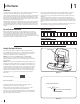
Assembling Hitch Bracket Assembly
1. Insert the ends of the rear support bracket
through the narrow slots at the rear of each
side support bracket. See Figure 4-1.
2. Secure folded tabs on rear support bracket to
side support brackets with a carriage screw
(ref. #7) and nylon lock nut (ref. #9). See Figure
4-1.
NOTE: The latches on the side support
brackets must be positioned with the opening
facing down on the outside of the bracket and
the tabs on the rear support bracket must be
facing up. See inset in Figure 4-1.
Figure 4-1
3. Flip over bracket assembly and mount the
bracket support assembly (ref. #2) on the
center hole of the rear support bracket using
the hex screw (ref. part #8) and flange lock nut
(ref. part #10). See Figure 4-2.
NOTE: It may be easier to leave the hex
screw and flange lock nut only finger tight
until mounted on the mower to ensure
components properly align when installing on
mower.
4. Attach the rubber grommet to the pin at the
bottom of the bracket support assembly. See
inset in Figure 4-2.
Figure 4-2
Installing Hitch Bracket Assembly
If your mower has a locking differential transmission
you will need to remove the Hitch Support Bracket
(789-00404) from the Fast Attach Support Bracket
Assembly (689-00463A) before mounting the hitch
to the tractor. To remove the bracket, use a T-30 torx
drive to remove the two torx screws securing the
assembly. See Figure 4-3.
Figure 4-3
1. Flip complete hitch bracket assembly over
when ready to install.
2. Pull back j-pins and lock open by twisting
them inward slightly and letting them rest
on the back of the rear support bracket. See
Figure 4-4.
Figure 4-4
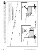
3. Slip the pin at the bottom of the bracket
support assembly into the hitch adapter on
the rear of the mower frame at a slight angle.
See 1 in Figure 4-5.
4. Ease the hitch bracket assembly forward over
the shoulder bolts on the sides of the mower
frame. See 2 in Figure 4-5.
5. Release the j-pins from the rear of the bracket
assembly. See 3 in Figure 4-5.
IMPORTANT! Make sure latches are fully
engaged with the shoulder bolts on the side
of the mower frame before attempting to
operate, or add any other attachment.
Figure 4-5
6. Fully tighten the hardware from step 3 if
previously left finger tight.
Install the bagger hanger assembly
1. Install the upright support bracket onto the
mounting assembly on the tractor by hooking
it over the cross mounting bracket. See Figure
4-6.
2. Align the upright support bracket with the
hole labeled “C”. See inset in Figure 4-6.
Figure 4-6
Note: Position “C” is the recommended
mounting position, but you may use other
mounting positions to accommodate other
attachments.
Required Tools
• 9/16” Socket Wrench (2) • 1/2” Socket Wrench (1) • M10 Socket Wrench (2) • T-30 Torx Bit (If Needed)