
Warranty

Form No. 769-23150
September 11, 2019
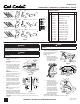
Contents of Carton
Ref Part # Description Qty
1 710-3168 Carriage Bolt 3/8-16 X 1.00 Gr5 4
2 710-3178 Carriage Bolt 3/8-16 X 0.75 Gr5 9
3 712-05007 Hex Flange Nuts 13
4 742-04278A Mulch Blade (48” Deck) 3
5 01005380 Mulch Blade (54” Deck) 3
6 01005381 Mulch Blade (60” Deck) 3
7 689-02359 Discharge Baffle (48” Deck) 1
8 689-02360 Discharge Baffle (54” Deck) 1
9 689-02362 Discharge Baffle (60” Deck) 1
10 703-07182A Center Bracket (48” Deck) 1
11 703-07194 Center Bracket (54” Deck) 1
12 703-07178A Center Bracket (60” Deck) 1
13 703-07210A Left Bracket (48” Deck) 1
14 703-07193A Left Bracket (54” Deck) 1
15 703-07177A Left Bracket (60” Deck) 1
Installation Sheet
19A70064100 (48”); 19A70065100 (54”); 19A70066100 (60”) -- Mulch Kit
13
4
5
6
7
8
9
10
11
12
14
15
1
2
3
48” Deck
54” Deck
60” Deck
Figure 1
CUB CADET LLC, P.O. BOX 361131 CLEVELAND, OHIO 44136-0019
Blade Installation
WARNING
Before beginning installation, place the tractor on a firm and level surface, set the
parking brake, place the PTO in the disengage (OFF) position, stop the tractor’s engine
and remove the ignition key to prevent unintended starting.
WARNING
Cutting blades are sharp. Always protect hands by wearing heavy leather work gloves
to grasp blades.
1. Remove cutting deck from beneath tractor as instructed in your Operator’s Manual.
2. Gently flip deck over to expose its
underside.
IMPORTANT: Flipping the deck will require
two people.
3. Place a block of wood between deck
housing baffle and cutting blade to
act as a stabilizer, then use a wrench
to remove hex flange nut securing
each blade to its spindle assembly. See
Figure 2.
IMPORTANT: Hex flange nuts have a
right-handed (normal) thread pattern. Do NOT
attempt to force nuts in opposite direction.
Doing so may damage nut.
4. Remove chute deflector baffle from
underside of deck by removing two
carriage bolts and flange lock nuts
that secure it to deck. See Figure 3.
5. When baffle is removed, re-install one
carriage bolt and flange lock nut into
deck in most central opening. See
Figure 3.
NOTE: Replacing hardware keeps material
from escaping the deck.
6. Replace blades with blades included in
kit. Be sure to install each blade with
side marked ‘‘Bottom’’ (or with a part
number stamped in it) facing the ground when mower is in operating position.
IMPORTANT: Use a torque wrench to tighten each blade spindle’s hex flange nut to between 90 ft-lb
and 110 ft-lb.
Baffle Installation
CAUTION
Do not remove cutting deck’s discharge chute when operating mower with mulch
kit installed.
1. Install center bracket using four
carriage bolts (710-3178) and four hex
flange nuts (712-05007). See Figure 4.
2. Install discharge baffle in the
following order:
a. Install discharge baffle to
underside of top of deck with
two carriage bolts (710-3168)
and two hex flange nuts
(712-05007). See Figure 5.
b. Working from inside out,
secure discharge baffle to
outside wall of deck with two
carriage bolts (710-3168) and
two hex flange nuts (712-
05007). See (1) in Figure 6.
c. Stabilize discharge baffle by
connecting it to previously
installed center bracket with
two carriage bolts (710-3178)
and two hex flange nuts (712-
05007). See (2) in Figure 6.
3. Install left baffle using three carriage
bolts (710-3178) and three hex flange nuts (712-05007). See Figure 7.
Figure 2
Figure 3
Figure 4
Figure 5
1
2
Figure 6
Figure 7