
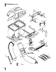
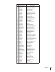
Replacement Part List


12 Section 4 — ASSembly & inStAllAtion
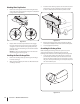
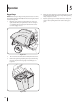
3. Install the chute discharge plate to the bottom side of the
deck opening, as seen in Figure 4-17, using two carriage
bolts (710-3168) supplied in hardware pack 689-00329.
Figure 4-17
4. Replace the discharge chute and secure with two flange
lock nuts (712-04065) included in the same hardware pack.
5. Securely tighten the hardware.
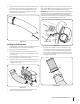
Assembling the Discharge Chute
Before installing the discharge chute onto your tractor, some
components must first be assembled onto the chute. The
following are the instructions for assembling the discharge chute.
1. Locate the chute elbow and install the grass-catcher pin
(911-04069) from hardware pack 689-00329 to the chute
elbow in the hole provided as shown in Figure 4-18. Secure
the grass-catcher pin with a flange lock nut (912-3027) from
the same hardware pack.
Figure 4-18
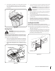
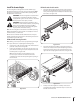
Attaching Chute Stop Bracket
1. Remove the carriage bolt and lock nut holding the chute
stop to the deck. See the left Inset of Figure 4-16. Retain the
carriage bolt for reinstallation.
Figure 4-16
2. Replace with new chute stop bracket, from the bagger
kit, at the same position on the deck. See the right Inset
of Figure 4-16. Secure with the carriage bolt previously
removed, and a 712-04065 flange lock nut from hardware
pack 689-00329.
NOTE: This chute stop bracket may stay on the unit even
when the bagger is not being used.
Installing the Chute Discharge Plate
1. Remove the discharge chute by removing the two flange
lock nuts securing it.
2. With a hammer, lightly tap the bolts out. Discard the bolts
and flange lock nuts.