Safe Operation Practices • Set-Up • Operation • Maintenance • Service • Troubleshooting • Warranty Operator’s Manual 52” Snow Blade WARNING READ AND FOLLOW ALL SAFETY RULES AND INSTRUCTIONS IN THIS MANUAL BEFORE ATTEMPTING TO OPERATE THIS MACHINE. FAILURE TO COMPLY WITH THESE INSTRUCTIONS MAY RESULT IN PERSONAL INJURY. CUB CADET LLC, P.O. BOX 361131 CLEVELAND, OHIO 44136-0019 Printed In USA Form No.
1 To The Owner Thank You Thank you for purchasing a Cub Cadet Snow Blade. It was carefully engineered to provide excellent performance when properly operated and maintained. Please read this entire manual prior to operating the equipment. It instructs you how to safely and easily set up, operate and maintain your machine. Please be sure that you, and any other persons who will operate the machine, carefully follow the recommended safety practices at all times.
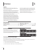
2 Assembly & Set-Up Contents of Carton 24 9 3 12 4 23 10 2 1 40 5 11 Hardware 19 8 17 21 25 30 29 13 35 15 37 39 38 36 41 14 20 31 28 26 27 16 33 34 32 18 6 7 22 3
Ref. Part Number Description Qty. 1 N/A Blade Assembly 1 2 N/A Blade Adjustment Handle Assembly 1 3 N/A Brace Bracket Assembly 1 4 N/A Lift Rod Assembly 1 5 603-05153 Lift Bracket Assembly 1 6 738-04128 * Shoulder Bolt, 3/8-16 x .500 x 2.
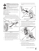
WARNING! Disengage the PTO, engage the brake lock, and stop the tractor engine before performing any preparation procedures. Place the tractor on a firm and level surface before beginning installation procedures. 6. WARNING! The exhaust system and surrounding areas are HOT. To avoid personal injury, allow the tractor to cool before beginning any blade installation procedures.
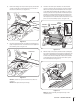
12. For 2014 and newer tractors, the lift handle will need to be replaced. Proceed with step 13 for 2014 and newer tractors, for 2012/13 tractors skip ahead to step 15. 13. Remove the hex screw and flange lock nut securing the handle to the deck lift shaft assembly and remove the handle. See Figure 2-4. 17. The three pedals will also have to be removed to get the floor board off the tractor.
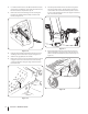
19. Remove the clevis pin, shoulder spacer and cotter pin that secure the blade mount bracket to the brace assembly. See Figure 2-8. 21. Re-install the brace assembly to the blade mount bracket using the clevis pin, shoulder spacer and cotter pin removed in step 19. 22. With the floor board still loose, remove the hex screws and flange lock nuts on each side of the front bumper. See Figure 2-10.
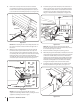
24. Remove the click pins and slide the rod out of the brace bracket assembly. Be sure not to lose the flange bearings when removing the rod. See Figure 2-12. 27. Replace the floor board and on the right side of the tractor mount the flange on the handle mount bracket to the frame with a hex washer screw (#15) and spacer (#31) as shown in Figure 2-14. Hex Washer Screw Handle Mount Bracket Flange Spacer Click Pins Rod Figure 2-12 25.
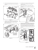
30. Remove the flange lock nuts, shoulder spacers, flat washers and hex screws that secure the lift plates on each side of the tractor to the frame. See Figure 2-16. 32. Hook the ends of the pivot brackets onto the shoulder spacers as shown in the inset of Figure 2-18. Then remove the bow-tie cotter pins and washers from the clevis pins on the lift bracket assembly (#5). If installing on a 2012-13 model, replace the clevis pin, washer and shoulder spacer with #36, 37 & 39 from the hardware pack.
34. Remove the cotter pin from the curved end of the lift rod assembly and slide the curved end into the front lift bracket on the blade assembly (#1). Replace the cotter pin to secure the lift rod assembly (#4) in place. See Figure 2-20. 36. Install the spring mount bracket (#7) on the underside of the floor board using a hex washer screw (#14) and flange lock nut (#21).
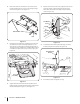
40. Slide the blade adjustment handle assembly (#2) into the eyebolt (#16) and attach it to the outer hole on the blade adjustment arm using a shoulder bolt (#28), flat washer (#27) and flange lock nut (#19). See Figure 2-24 . 42. Secure the cable to the blade adjustment handle assembly (#2) with the two cable ties (#25) provided. See Figure 2-26. Shoulder Bolt Flat Washer Outer Hole Flange Lock Nut Cable Ties Figure 2-26 Blade Removal Figure 2-24 41.
3 Controls & Features Deck Lift Handle Blade Release Cable Lever Shave Plate Blade Blade controls and features are illustrated in Figure 3-1 and described below. Figure 3-1 Blade The blade is used to push snow/dirt/gravel, etc. and can be angled left or right and raised or lowered. Deck Lift Handle The deck lift handle is located on the RH console of the tractor and is used to raise and lower the blade.
4 Operation Operation NOTE: The blade is designed for clearing snow, leveling soft dirt or sand and other light duty dozer jobs. The spring trip release protects the blade, tractor and operator from severe shock loads when the blade comes in contact with curbs and other obstacles. The blade has a reversible and replaceable cutting edge. WARNING! Before operating the tractor, familiarize yourself with the SAFE OPERATION PRACTICES in the rider manual starting on page 3.
5 Maintenance & Adjustments Maintenance Shave Plate Lubrication If the shave plate becomes worn, reverse or replace the bar as follows (See Figure 5-2): Periodically lubricate the pivot points between the A-frame and pivot plate with a good grade of grease. Periodically spray lube the pivot latch components. Adjustments Skid Shoes NOTE: Adjust the skid shoes so the blade cutting edge just clears the pavement when being used for snow removal.
Notes 6 15
Section 6— Notes
Section 6 — Notes 17
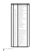
7 Illustrated Parts List 8 43 13 35 A 77 49 43 46 13 38 33 26 21 17 45 50 60 60 3 14 4 B 31 27 53 27 1 72 34 75 29 61 40 51 16 52 67 64 24 55 54 9 25 19 42 19 58 45 5 15 40 72 78 43 69 10 52 45 63 41 12 1 52 39 43 18 11 52 A 30 59 36 71 6 7 56 70 20 12 57/80 79 47 65 23 26 14 68 2 26 48 22 76 50 51 44 28 49 18 50 37 43 43 18 73 B 15 62 62 66 81 32 43
Ref. Part Number Description Ref.
CUB CADET LLC MANUFACTURER’S LIMITED WARRANTY FOR SEPARATELY SOLD ATTACHMENTS AND ACCESSORIES IMPORTANT: To obtain warranty coverage owner may be required to present an original proof of purchase and applicable maintenance records to the servicing dealer. Please see the operator’s manual for information on required maintenance and service intervals.