
Use and Care Manual

Section 2— ASSembly & Set-Up10
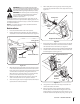
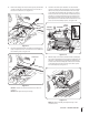
34. Remove the cotter pin from the curved end of the lift
rod assembly and slide the curved end into the front lift
bracket on the blade assembly (#1). Replace the cotter pin
to secure the lift rod assembly (#4) in place. See Figure 2-20.
Cotter Pin
Lift Rod
Figure 2-20
NOTE: When installing the lift rod assembly (#4) make sure
the curved end of the rod faces towards the right side of
the tractor.
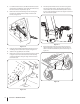
35. With the tractor on flat/level ground, place the deck lift
handle into the #2 position. Remove the cotter pin and
clevis pin from the clevis adjustment assembly on the lift
rod assembly (#4). Line up the holes in the lift rod assembly
(#4) and the holes on the underside of the lift bracket
assembly (#5). Slide the clevis pin through both assemblies
and secure in place with the cotter pin. See Figure 2-21.
Clevis Pin
Clevis
Adjustment
Assembly
Cotter Pin
Lift
Bracket
Assembly
Figure 2-21
NOTE: If necessary, the length of the lift rod can be
adjusted to better align with the hole by rotating the clevis
adjustment assembly to the left or right.
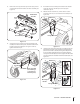
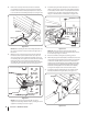
36. Install the spring mount bracket (#7) on the underside of
the floor board using a hex washer screw (#14) and flange
lock nut (#21). The hex washer screw (#14) should be lined
up with a hole in the floor of the frame that aligns with
flanges on the lift bracket assembly (#5). See Figure 2-22.
Hex Washer Screw
Flange Lock Nut
Extension Spring
Flange
Spring Mount Bracket
Eye Bolt
Sems Nut
Figure 2-22
NOTE: On earlier models, to install the spring mount
bracket the diameter of the hole in the frame may need to
be increased by using a ⁄” drill bit.
37. Raise the deck lift to the highest operating position.
38. When the spring mount bracket (#7) is installed, hook one end
of the extension spring (#26 for tractors with 50” and 54” deck
or #41 for 42” and 46” decks) into the hole on the bracket.
Hook the other end through the eye bolt (#16). Then feed the
threaded end of the eye bolt (#16) through the flange in the
lift bracket assembly (#5) and secure with a sems nut (#18).
See Figure 2-22. Repeat on the other side of the tractor.
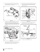
39. Install the eyebolt assembly (#8) onto the handle mount
bracket (#11) with the wing nut (#20). See Figure 2-23.
Wing Nut
Eyebolt Assembly
Figure 2-23