
Use and Care Manual

Section 2 — ASSembly & Set-Up
5
WARNING! Disengage the PTO, engage the brake
lock, and stop the tractor engine before performing any
preparation procedures. Place the tractor on a firm and
level surface before beginning installation procedures.
WARNING! The exhaust system and surrounding
areas are HOT. To avoid personal injury, allow the
tractor to cool before beginning any blade
installation procedures.
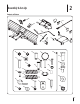
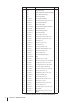
NOTE: The hardware used to install some components on the
snow blade has been loosely installed for shipping purposes. To
assemble the blade it may be necessary to remove this hardware
to complete installation.
NOTE: Do not remove the deck or other attachment from the
tractor until instructed below.
Blade Installation
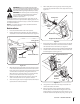
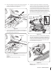
1. Place the deck lift handle in the lowest position.
2. Remove the flex lock nut and pivot cup on the deck lift rod
and slide the rod out of the rod mount bracket. See Figure 2-1.
Flex Lock Nut
Pivot Cup
Deck Lift Rod
Nylon Sleeve
Rod Mount Bracket
Figure 2-1
3. When the deck lift rod has been removed, the nylon sleeve
in the rod mount bracket must also be removed. From the
front of the tractor, pull forward on the forward drive pedal
and slide the sleeve upwards, through the frame hole.
When the narrow end of the sleeve is clear of the bracket,
pull it out of the bracket to the left. See Figure 2-1.
4. With the deck lift still in the lowest position, remove the
deck as instructed in the tractor operator’s manual.
5. After removing the deck, the height index bracket must be
replaced with a reinforced bracket.
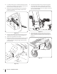
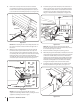
6. With a utility knife cut along the top of the existing deck
lift handle grip until the handle can be easily removed. See
Figure 2-2.
Deck Lift
Handle
Grip
Cut Grip Here
Hex Washer Screws
Height Index Bracket
Figure 2-2
7. Remove the two hex washer screws that secure the height
index bracket to the frame. Save the hex washer screw for
the installation of the new bracket. See Figure 2-2.
8. Slide the bracket out of the console and off the deck lift handle.
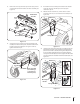
9. Slide the new reinforced bracket (#9) onto the handle and
back through the console. Figure 2-3.
Hex
Washer
Screws
Height Index Bracket
Lift Arm
Stiffener
Brackets
Hex Screw
Flange
Lock
Nut
Figure 2-3
10. Using the hex screws removed in step 7, install the new
reinforced bracket to the frame.
11. On 2012 and 2013 models, Install the lift arm stiffener
brackets (#23) on the deck lift arm using the hex screws
(#34) and flange lock nuts (#33) as shown in Figure 2-3. For
2014 and newer models skip this step and go onto step 12.