
Use and Care Manual

Section 2 — ASSembly & Set-Up
7
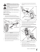
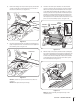
19. Remove the clevis pin, shoulder spacer and cotter pin that
secure the blade mount bracket to the brace assembly. See
Figure 2-8.
Clevis
Pins
Shoulder
Spacer
Shoulder
Spacer
Cotter
Pin
Cotter
Pin
Brace Assembly
Blade Mount
Bracket
Figure 2-8
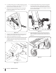
20. Using the hex screw removed in step 18 and flange lock
nut (#19) from the hardware pack, install the blade mount
bracket onto the front bumper. See Figure 2-9. Do not
tighten the hardware yet.
Flange Lock Nuts
(Use new flange
lock nuts from
hardware pack)
Hex Screws
Blade Mount
Bracket
Figure 2-9
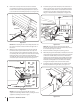
21. Re-install the brace assembly to the blade mount bracket
using the clevis pin, shoulder spacer and cotter pin
removed in step 19.
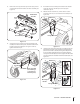
22. With the floor board still loose, remove the hex screws
and flange lock nuts on each side of the front bumper. See
Figure 2-10.
Hex Screws
Flange Lock Nuts
Figure 2-10
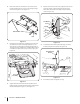
23. Using the hex screws removed in step 22 and flange lock nuts
(#19) from the hardware pack, install the mounting brackets
(#10 for tractors with a cast axle (the longer bracket), and #12
for tractors with a fabricated axle, the shorter bracket with
notch)) to the front bumper, but do not tighten. The fabricated
axle also requires the installation of four flat washers (#32). See
Figure 2-11.
Hex Screws
Mounting
Bracket
Flange Lock Nuts
Cast Axle
Bracket
Fabricated
Axle Bracket
Flat
Washer
Figure 2-11