
Use and Care Manual

Section 2— ASSembly & Set-Up8
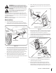
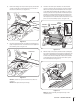
24. Remove the click pins and slide the rod out of the brace
bracket assembly. Be sure not to lose the flange bearings
when removing the rod. See Figure 2-12.
Click Pins
Rod
Figure 2-12
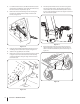
25. Lift the back end of the brace assembly and line the holes
up with the holes in the mounting brackets (#10 or 12).
Then slide the rod through the mounting brackets (#10 or
12), flange bearings and the brace assembly. When in place,
re-install the click pins in the rod to secure it in place. See
Figure 2-13.
Mounting Brackets
Brace
Assembly
Figure 2-13
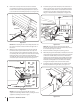
26. Tighten the front blade mount bracket hardware. Then
tighten the left and right hand axle brackets and the blade
mount bracket. Refer to Figure 2-9 and Figure 2-11.
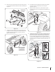
27. Replace the floor board and on the right side of the tractor
mount the flange on the handle mount bracket to the
frame with a hex washer screw (#15) and spacer (#31) as
shown in Figure 2-14.
Hex Washer
Screw
Spacer
Flange
Handle Mount
Bracket
Figure 2-14
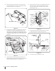
28. Install the handle mount bracket (#11) using a shoulder
bolt (#6) and jam lock nut (#38). See Figure 2-15.
Handle Mount
Bracket
Shoulder Bolt
Jam
Lock
Nut
Figure 2-15
29. Re-install the pedals and tighten securely.