
Use and Care Manual

Section 2 — ASSembly & Set-Up
9
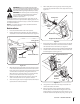
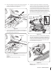
30. Remove the flange lock nuts, shoulder spacers, flat washers
and hex screws that secure the lift plates on each side of
the tractor to the frame. See Figure 2-16.
Lift Plate
Flange
Lock
Nut
Shoulder Spacer
Flat Washer
Hex Screw
Figure 2-16
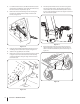
31. Re-install the lift plates with an additional shoulder spacer
(#30) and replace the hex screw with a hex screw (#13) from
the hardware pack. See Figure 2-17.
Hex Screw
Shoulder Spacer
Figure 2-17
NOTE: Be careful not to pinch the wire harness when re-
installing.
NOTE: The lift plates should pivot freely.
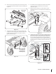
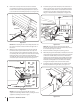
32. Hook the ends of the pivot brackets onto the shoulder
spacers as shown in the inset of Figure 2-18. Then remove
the bow-tie cotter pins and washers from the clevis pins
on the lift bracket assembly (#5). If installing on a 2012-13
model, replace the clevis pin, washer and shoulder spacer
with #36, 37 & 39 from the hardware pack. Insert the pins
back into the shoulder spacers and into the rear holes on
the lift plates and re-install the washers and bow-tie cotter
pins to secure the assembly in place. See Figure 2-18.
Bow-Tie
Cotter Pin
Clevis Pin
Lift Plate
Pivot
Bracket
Clevis Pin
Shoulder Spacer
Washer
Figure 2-18
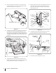
33. With the help of an assistant, slide the blade assembly (#1)
into position beneath the brace bracket assembly (#3). Line
the holes on the blade frame assembly up with the holes
in the brace bracket assembly (#3) and insert the shoulder
screws (#30) through each hole and secure with a pair of
hex lock nuts (#22). See Figure 2-19.
Hex Lock Nuts
Shoulder Screws
Figure 2-19
NOTE: The blade assembly should pivot freely on the
shoulder screws.