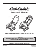
Safe Operation Practices • Set-Up • Operation • Maintenance • Service • Troubleshooting • Warranty Operator’s Manual Model 221 HP Model 221 LHP Single-Stage Snow Thrower — Models 221 HP & 221 LHP WARNING READ AND FOLLOW ALL SAFETY RULES AND INSTRUCTIONS IN THIS MANUAL BEFORE ATTEMPTING TO OPERATE THIS MACHINE. FAILURE TO COMPLY WITH THESE INSTRUCTIONS MAY RESULT IN PERSONAL INJURY. CUB CADET LLC, P.O. BOX 361131 CLEVELAND, OHIO 44136-0019 Printed In USA Form No.
1 To The Owner Thank You Thank you for purchasing a Cub Cadet Snow Thrower. It was carefully engineered to provide excellent performance when properly operated and maintained. If applicable, the power testing information used to establish the power rating of the engine equipped on this machine can be found at www.opei.org or the engine manufacturer’s web site. Please read this entire manual prior to operating the equipment.
Important Safe Operation Practices 2 WARNING! This symbol points out important safety instructions which, if not followed, could endanger the personal safety and/or property of yourself and others. Read and follow all instructions in this manual before attempting to operate this machine. Failure to comply with these instructions may result in personal injury. When you see this symbol.
Safe Handling of Gasoline 5. To avoid personal injury or property damage use extreme care in handling gasoline. Gasoline is extremely flammable and the vapors are explosive. Serious personal injury can occur when gasoline is spilled on yourself or your clothes which can ignite. Wash your skin and change clothes immediately. Never run an engine indoors or in a poorly ventilated area. Engine exhaust contains carbon monoxide, an odorless and deadly gas. 6.
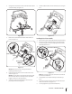
Clearing a Clogged Discharge Chute Hand contact with the rotating impeller inside the discharge chute is the most common cause of injury associated with snow throwers. Never use your hand to clean out the discharge chute. To clear the chute: 1. SHUT THE ENGINE OFF! 2. Wait 10 seconds to be sure the impeller blades have stopped rotating. 3. Always use a clean-out tool, not your hands. Maintenance & Storage 1. Never tamper with safety devices. Check their proper operation regularly.
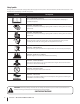
Safety Symbols This page depicts and describes safety symbols that may appear on this product. Read, understand, and follow all instructions on the machine before attempting to assemble and operate. Symbol Description READ THE OPERATOR’S MANUAL(S) Read, understand, and follow all instructions in the manual(s) before attempting to assemble and operate WARNING— ROTATING BLADES Keep hands out of inlet and discharge openings while machine is running.
3 Assembly & Set-Up Contents of Carton • One Snow Thrower • One Chute Assembly • One Chute Rotation Control Assembly • Two Ignition Keys • One 20 oz. Bottle 5W-30 Oil • One Snow Thrower Operator’s Manual • One Engine Operator’s Manual NOTE: This Operator’s Manual covers several models. Snow thrower features may vary by model. Not all features in this manual are applicable to all snow thrower models and the snow thrower depicted may differ from yours. 2.
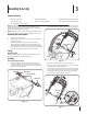
Installing the Chute 1. 3. On the 221 HP model place the chute handle on the lower chute as shown in Figure 3-4. Skip to step 2 for 221 LHP models. Be certain that the handle is aligned in the channel on the chute and the tabs snap into place. Align the holes in the chute base with the holes in the lower chute and secure with the previously removed hex washer screws. See Figure 3-6. Channel Figure 3-6 Tab Figure 3-4 2. Remove the hex washer screws in the chute base. See Figure 3-5.
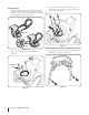
2. Using the four hex washer screws, install the chute rotation control assembly. See Figure 3-8. 6. Slide the rubber bellow over the universal joint. See Figure 3-10. Rubber Bellow Figure 3-8 3. Figure 3-10 Remove the screw and hex lock nut from the universal joint. See Figure 3-9. Installing the Recoil Starter Handle 1. Remove the eye bolt and handle knob from the manual bag. 2. Place the eye bolt and handle knob on the upper handle as shown in Figure 3-11.
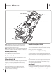
4 Controls & Features Headlight Chute Tilt Control Auger Control Recoil Starter Handle Chute Rotation Control Chute Assembly Model 221 LHP Shown Auger Shave Plate NOTE: This Operator’s Manual covers several models. Snow thrower features may vary by model. Not all features in this manual are applicable to all snow thrower models and the snow thrower depicted may differ from yours. NOTE: All references to the left or right side of the snow thrower are from the operator’s position.
5 Operation NOTE: Refer to the Engine Operator’s Manual for instruction on starting, stopping and operating the engine. Engaging the Auger 1. To engage the auger and start throwing snow, squeeze the auger control against the handle. Release to stop the auger. See Figure 5-1. Chute Controls (Model 221 LHP) Refer to Figure 5-2 for chute controls.
Chute Control (Model 221 HP) Refer to Figure 5-3 for the chute controls. Chute Control Handle Upper Chute Wing Nut Figure 5-3 To increase the angle/distance snow is thrown, pull up/back on the upper chute. To decrease the angle/distance snow is thrown, push down/forward on the upper chute. To rotate the chute to the left, turn the chute control handle to the right. To rotate the chute to the right, turn the chute control handle to the left.
6 Maintenance & Adjustments Adjustments Control Cable WARNING! Before servicing, repairing or inspecting the snow thrower, disengage the auger control. Stop the engine and remove the key to prevent unintended starting. Shave Plate To check the adjustment of the shave plate, place the snow thrower on a level surface. The wheels, shave plate and auger should all contact the level surface. Note that if the shave plate is adjusted too high, snow may blow under the housing.
Engine Refer to the Engine Operators manual packed separately with your snow thrower for maintenance and adjustment information on your engine. 1. To access the oil drain and spark plug it is necessary to remove the lower panel. 2. Remove the three screws that secure the lower panel. Remove the lower panel by lifting up on the panel to free the tabs at the bottom of the panel from the tab slots and then pull back. See Figure 6-3.
7 Service Replacing Belt 1. Run the snow thrower until the fuel tank is empty. 2. Pull the recoil starter handle until resistance is felt. Then tip the snow thrower back until it rests on the handles. 3. Slide a board up through the auger and through the chute to secure the auger in place. 4. Remove the belt cover by removing the three hex washer screws and one hex lock screw that secure it to the frame. See Figure 7-1. Hex Lock Screw 6. Remove the auger pulley and the belt. 7.
Replacing Auger Paddles Replacing Shave Plate The snow thrower auger’s rubber paddles are subject to wear and should be replaced if any signs of excessive wear are present. The shave plate is attached to the bottom of the auger housing and is subject to wear. It should be checked periodically. There are two wearing edges and the shave plate can be reversed.
8 Troubleshooting Problem Cause Remedy Excessive vibration 1. Loose parts or damaged auger. 1. Stop engine immediately and disconnect spark plug wire. Check for possible damage. Tighten all bolts and nuts. Repair as needed. If the problem persists, take snow thrower to an authorized service dealer. Snow thrower fails to selfpropel 1. Auger control cable out of adjustment. 1. Adjust auger control cable as shown in Maintenance & Adjustments section. 2. Auger drive belt loose or damaged. 2.
9 Replacement Parts Component Part Number and Description 731-08171 Shave Plate 954-04050 Belt 753-06469 Rubber Auger Paddle Kit (Includes 2 paddles and 12 hex washer screws) 746-04701 Clutch Cable 634-04665 731-08570 Wheel Assembly, 8 x 2 Hupcap 925-1629 Lamp, #1156 (Model 221 LHP) 751-14006 Fuel Cap 731-05632 Key Phone (800) 965-4CUB to order replacement parts or a complete Parts Manual (have your full model number and serial number ready).
Notes 10 19
CUB CADET LLC MANUFACTURER’S LIMITED WARRANTY FOR SNOW THROWERS, LOG SPLITTERS CHIPPER-SHREDDERS, CHIPPER-SHREDDER VACUUMS AND JET SWEEPS The limited warranty set forth below is given by Cub Cadet LLC with respect to new merchandise purchased and used in the United States, its possessions and territories, and by MTD Products Limited with respect to new merchandise purchased and used in Canada and/or its territories and possessions. a.