OPERATOR’S MANUAL Chipper Shredder Vacuum Model Number 24A-030E100 IMPORTANT: READ SAFETY RULES AND INSTRUCTIONS CAREFULLY Warning: This unit is equipped with an internal combustion engine and should not be used on or near any unimproved forestcovered, brush-covered or grass-covered land unless the engine’s exhaust system is equipped with a spark arrester meeting applicable local or state laws (if any). If a spark arrester is used, it should be maintained in effective working order by the operator.
TABLE OF CONTENTS Content Page Important Safe Operation Practices................................................................... 3 Assembling Your Chipper Shredder Vacuum .................................................... 5 Know Your Chipper Shredder Vacuum .............................................................. 7 Operating Your Chipper Shredder Vacuum ....................................................... 8 Maintaining Your Chipper Shredder Vacuum............................................
SECTION 1: IMPORTANT SAFE OPERATION PRACTICES WARNING: This symbol points out important safety instructions which, if not followed, could endanger the personal safety and/or property of yourself and others. Read and follow all instructions in this manual before attempting to operate this machine. Failure to comply with these instructions may result in personal injury. When you see this symbol - heed its warning.
SAFE HANDLING OF GASOLINE: • Do not allow an accumulation of processed material to build up in the discharge area as this will prevent proper discharge. To avoid personal injury or property damage use extreme care in handling gasoline. Gasoline is extremely flammable and the vapors are explosive. Serious personal injury can occur when gasoline is spilled on yourself or your clothes which can ignite. Wash your skin and change clothes immediately.
WARNING - YOUR RESPONSIBILITY: Restrict the use of this power machine to persons who read, understand and follow the warnings and instructions in this manual and on the machine. NOTE: Not all safety labels shown may apply to your chipper shredder vacuum. SECTION 2: ASSEMBLING YOUR CHIPPER SHREDDER VACUUM IMPORTANT: This unit is shipped without gasoline or oil in the engine. Be certain to service engine with gasoline and oil as instructed in the separate engine manual before operating your mower.
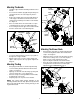
Attaching The Handle • • • • • Lower Handle Unfold the upper handle until it aligns with the lower handle. Secure the two handles by tightening the wing nuts (carriage bolts must be seated properly into the handle). Remove the hairpin clips from the handle brackets on the chipper shredder vacuum and remove the carriage bolts and wing nuts from the lower handle. See Figure 2. Place each bottom hole in lower handle over pins on handle brackets and secure with hairpin clips.
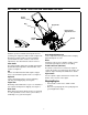
SECTION 3: KNOW YOUR CHIPPER SHREDDER VACUUM Starter Handle Bag Bag Handle Nozzle Height Adjustment Lever Chipper Chute Nozzle Blower Chute Figure 5 Nozzle Height Adjustment Lever Read this operator’s manual and safety rules before operating your chipper shredder vacuum. Compare the illustrations in Figure 5 with your unit to familiarize yourself with the location of various controls and adjustments. Save this manual for future reference.
SECTION 4: OPERATING YOUR CHIPPER SHREDDER VACUUM WARNING: The operation of any chipper shredder vacuum can result in foreign objects being thrown into the eyes, which can damage your eyes severely. Always wear the safety glasses provided with this unit or eye shields before chipping or blowing and while performing any adjustments or repairs. • • • • Grasp bag handle with one hand and pull lock rod on mounting bracket with other hand toward engine to release. Remove bag from rim of the discharge opening.
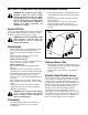
Nozzle Height Adjustment The nozzle can be adjusted to any five positions, ranging from 5/8” to 3 3/4” ground clearance. The nozzle height has to be adjusted according to the conditions. Move the height adjustment levers forward or backward to adjust the nozzle upwards or downwards. See Figure 8. NOTE: In general, raise the nozzle height to vacuum a think layer of leaves or to operate with the blower chute and lower the nozzle height for smoother surfaces.
Removing The Flail Screen WARNING: Always stop engine and disconnect spark plug wire before cleaning, lubricating or doing any kind of maintenance on your machine. If the discharge area becomes clogged, remove the flail screen and clean area as follows: • Lubrication • Wheels: Lubricate each wheel shoulder screw once a season with light oil. See Figure 9. • Nozzle height adjustment levers: Lubricate the pivot points of the nozzle height adjustment levers once a season with light oil. See Figure 9.
NOTE: When tipping the unit, empty the fuel tank and keep spark plug side up. • • • • Disconnect the spark plug wire and ground it away from the spark plug. Remove the front hubcaps, shoulder screws, wave washers, and bell washers that attach to the front wheels. See Figure 12. Remove the shoulder screws that go through the pivot arms and height bracket adjusters to the front support brace. Pivot Arm • Remove lock nut that secures flail screen to the lower housing.
SECTION 6: TROUBLESHOOTING Problem Engine fails to start Cause Remedy 1. Spark plug wire disconnected. 2. Fuel tank empty or stale fuel. 3. Throttle control lever not in correct starting position. (If Equipped) 4. Choke not in CHOKE position. 5. Blocked fuel line. 6. Faulty spark plug. 1. Connect wire to spark plug. 2. Fill tank with clean, fresh gasoline. 3. Move throttle lever to FAST position. 1. Spark plug wire loose. 2. Unit running on CHOKE. 4. Water or dirt in fuel system. 5. Dirty air cleaner.
NOTES 13
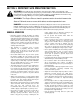
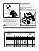
Model 24A-030E100 1 2 3 41 4 39 12 5 11 6 8 10 7 9 13 13 14 17 19 18 15 7 16 20 5 7 21 16 22 23 25 24 26 27 30 28 31 29 32 33 34 35 36 36 37 38 36 14
Model 24A-030E100 Ref. No. 1. 2. 3. 4. 5. 6. 7. 8. 9. 10. 11. 12. 13. 14. 15. 16. 17. 18. 19. 20. 21. Part No. 725-1700 725-3166 710-0224 629-0920 710-0604 714-0104 736-0264 732-0962 781-0778 747-1153 710-3008 681-0122 726-0454 736-0607 710-0502A 710-0969 710-3195 710-3025 710-0604A 781-0720 710-1054 Ref. No. Part Description Switch Cover Safety Switch Hex Washer Screw #10-16 x .50 Wire Harness Hex Washer Screw 5/16-18 x .625 Cotter Pin Flat Washer.330 ID x.
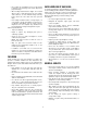
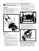
Model 24A-030E100 1 2 4 3 5 7 35 5 8 6 9 11 10 9 11 13 12 15 14 12 16 17 19 12 12 14 23 17 25 26 29 22 33 21 18 30 14 18 17 20 27 34 28 31 32 33 21 16
Model 24A-030E100 Ref. No. 1. 2. 3. 4. 5. 6. 7. 8. 9. 10. 11. 12. 13. 14. 15. 16. 17. Part No. 720-0295 749-0438C 720-0279 710-1205 720-0276 710-1174 749-0907A 664-0090 711-1293 712-0397 710-0703 726-0453 781-0777 712-3004A 714-0104 681-0155 681-0156 710-3025 Ref. No. Part Description Foam Grip Upper Handle Knob Eye Bolt Handle Knob 5/16-18 Carriage Bolt Lower Handle Bag Assembly Studs Wing Nut 1/4-20 Carriage Screw 1/4-20 x .
MANUFACTURER’S LIMITED WARRANTY FOR: TWO-YEAR RESIDENTIAL ONE-YEAR COMMERCIAL Proper maintenance of your Cub Cadet equipment is the owner’s responsibility. Follow the instructions in your operator’s manual for correct lubricants and maintenance schedule. Your Cub Cadet dealer carries a complete line of quality lubricants and filters for your equipment’s engine, transmission, chassis and attachments.