Safe Operation Practices • Set-Up • Operation • Maintenance • Service • Troubleshooting • Warranty Operator’s Manual Log Splitter — Model Series 510 thru 570 WARNING READ AND FOLLOW ALL SAFETY RULES AND INSTRUCTIONS IN THIS MANUAL BEFORE ATTEMPTING TO OPERATE THIS MACHINE. FAILURE TO COMPLY WITH THESE INSTRUCTIONS MAY RESULT IN PERSONAL INJURY. MTD LLC, P.O. BOX 361131 CLEVELAND, OHIO 44136-0019 Printed In USA Form No.
1 To The Owner Thank You Thank you for purchasing a Log Splitter manufactured by MTD LLC. It was carefully engineered to provide excellent performance when properly operated and maintained. Please read this entire manual prior to operating the equipment. It instructs you how to safely and easily set up, operate and maintain your machine. Please be sure that you, and any other persons who will operate the machine, carefully follow the recommended safety practices at all times.
2 Important Safe Operation Practices WARNING: This symbol points out important safety instructions which, if not followed, could endanger the personal safety and/or property of yourself and others. Read and follow all instructions in this manual before attempting to operate this machine. Failure to comply with these instructions may result in personal injury. When you see this symbol.
14. This machine should be used for splitting wood only, do not use it for any other purpose. 3. Do not operate machine while under the influence of alcohol, drugs, or medication. 15. Follow the instructions in the manual(s) provided with any attachment(s) for this machine. 4. Never allow anyone to operate this machine without proper instruction. 5. Always operate this machine with all safety equipment in place and working. Make sure all controls are properly adjusted for safe operation. 6.
13. Keep your work area clean. Immediately remove split wood around the machine so you do not stumble over it. 14. Do not change the engine governor settings or overspeed the engine. The governor controls the maximum safe operating speed of the engine. 15. Never move this machine while the engine is running. 16. This machine should not be towed on any street, highway or public road without checking the existing federal, state, or local vehicle requirements.
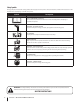
Safety Symbols This page depicts and describes safety symbols that may appear on this product. Read, understand, and follow all instructions on the machine before attempting to assemble and operate. Symbol Description READ THE OPERATOR’S MANUAL(S) Read, understand, and follow all instructions in the manual(s) before attempting to assemble and operate WARNING— CRUSHING HAZARD Keep hands away from wedge, end plate, partly split wood and moving parts.
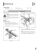
3 Assembly & Set-Up Contents of Carton • One Log Splitter • One Tongue Assembly • One Engine Operator’s Manual • One Tail Light Kit (If equipped) NOTE: This Operator’s Manual covers several models. Log splitter features may vary by model. Not all features in this manual are applicable to all log splitter models and the log splitter depicted may differ from yours. • One Operator’s Manual Attaching the Tongue 1. WARNING! Use extreme caution unpacking this machine.
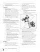
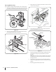
3. Connecting Cylinder to Beam The log splitter is shipped with the beam in the vertical position. 1. Disconnect the log cradle from the beam on the side of the control valve. See Fig. 3-5. Pull out the vertical beam lock, rotate it back, and pivot the beam into the horizontal position until it locks. See Fig. 3-3. Screws Log Cradle Vertical Beam Lock Figure 3-5 4. Figure 3-3 2. Lift and slide the cylinder up to the top of the beam and into the weld brackets. See Fig. 3-6.
Tail Light Installation (If equipped) 4. The mounting brackets for the tail light are installed. Refer to the installation sheet included with the tail light kit to mount the lights and route the harness. Replace the vented dipstick securely, tightening it until the top of the threads are flush with the top of the pipe. 5. Set-Up Disconnect the spark plug and prime the pump by pulling the recoil starter as far as it will go. Repeat approximately 10 times. 6.
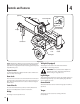
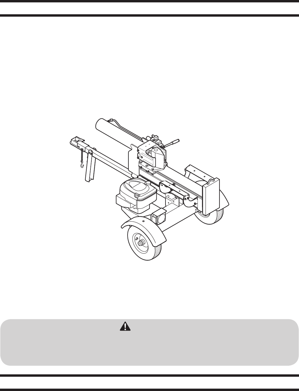
4 Controls and Features Cylinder Log Dislodger Control Handle Horizontal Beam Lock Beam Assembly Tongue Wedge Jack Stand Vertical Beam Lock Log Cradle Tail Light Figure 4-1 NOTE: This Operator’s Manual covers several models. Log splitter Tail Light (If equipped) features may vary by model. Not all features in this manual are The tail light’s are located on the back of the frame for applicable to all log splitter models and the log splitter depicted transportation and towing purposes.
5 Operation Starting the Engine WARNING! Read, understand and follow all instructions and warnings on the machine and in this manual before operating. WARNING! Wear leather work gloves, safety shoes, and safety glasses when operating a log splitter. Ensure safe footing. Stopping the Engine 1. Move the throttle control (if equipped) to the STOP or OFF position. 2. Turn off the engine switch, if so equipped. Using the Log Splitter 1.
c. c. Stand in front of the log splitter to operate the control handle and to stabilize the log. See Fig. 5-2. Figure 5-4 Figure 5-2 4. To place the beam in the Horizontal Position proceed as follows: a. Pull the vertical beam lock out and rotate it down. Pivot the beam to the horizontal position. b. The horizontal beam lock is self-locking. The spring loaded lock will snap into place when the beam is lowered into position. See Fig. 5-3. 4.
4. Secure with the spring clip and clevis pin previously removed. See Fig. 5-5. Operating Tips Always: Spring Clip 1. Use clean fluid and check the fluid level regularly. 2. Use an approved hydraulic fluid. Approved fluids include Shell Tellus® 32 Hydraulic Fluid, Dexron® III / Mercon® automatic transmission fluid, Pro-Select™ AW-32 Hydraulic Oil or 10WAW-ISO viscosity grade 32 hydraulic oil. NOTE: It is not recommended that fluids be mixed. 3. Use a filter (clean or replace regularly). 4.
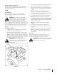
6 Maintenance & Adjustments WARNING! Do not make any adjustments without first stopping the engine, disconnecting the spark plug wire and grounding it against the engine. Always wear safety glasses during operation or while performing any adjustments or repairs. 2. Carefully unthread the inlet filter and clean it with penetrating oil. See Fig. 6-1. Maintenance Engine Refer to the Engine Operator’s Manual packed with your log splitter for all engine maintenance.
9. Refill the reservoir within range marked on the dipstick. See Fig. 6-2. Adjustments Gib Adjustment Dipstick Periodically remove and replace the gibs — spacers — between the wedge assembly and the back plate. NOTE: The gibs may be rotated and/or turned over for even wear. 1. MAX Loosen the lock nuts under each back plate and slide the gibs out. See Fig. 6-3. MIN Lock Nut Wedge Hydraulic Fluid Only Jam Nut Gib Adjustment Bolt Figure 6-2 10.
Wedge Assembly As normal wear occurs and there is excessive “play” between the wedge and beam, adjust the bolts on the side of the wedge assembly to eliminate excess space between the wedge and the beam. 1. Loosen the jam nuts on the two adjustment bolts on the side of the wedge. See Fig. 6-3. 2. Turn the adjustment bolts in until snug and then back them off slowly (approximately 1-1⁄2 turns) until the wedge assembly will slide on the beam. 3.
Notes 17
7 Troubleshooting Problem Engine fails to start Engine runs erratic Engine Overheats Cylinder rod will not move 18 Cause Remedy 1. Spark plug wire disconnected. 1. Connect wire to spark plug. 2. Fuel tank empty or stale fuel. 2. Fill tank with clean, fresh gasoline. 3. Choke not in CHOKE position. 3. Move choke to CHOKE position. 4. Faulty spark plug. 4. Clean, adjust gap, or replace. 5. Blocked fuel line. 5. Clean fuel line. 6. Throttle control lever not in correct starting position. 6.
Problem Slow cylinder shaft speed while extending and retracting Leaking Cylinder Engine runs but wood will not split or wood splits too slowly Engine stalls during splitting Engine will not turn or stalls under low load conditions Leaking pump shaft seal Cause Remedy 1. Gear sections damaged. 1. See authorized service dealer. 2. Excessive pump inlet vacuum. 2. Make certain pump inlet hoses are clear and unblocked-use short, large diameter inlet hoses. 3. Slow engine speed. 3.
8 Illustrated Parts List 25 A 7 13 24 28 8 2 4 1 9 10 6 5 11 3 22 16 A A 67 15 21 14 12 18 BB 25 28 29 24 23 27 26 40 36 43 40 37 40 38 41 17 47 39 66 37 41 48 B 29 49 42 24 CC 20 32 46 44 30 40 58 37 35 56 82 61 59 D 69 55 D D 72 67 24 66 75 68 CC 50 54 51 63 76 72 75 52 57 84 85 74 53 79 77 73 78 60 71 64 65 81 70 80 62 20 31 19 45 62 34 33 83
Ref Part Number Ref Part Number 1 711-04585 Clevis Pin, .25 x 1.00 Description 36 681-04030 Hitch Coupling Assembly Description 2 913-04036 Handle Valve Link 37 710-0521 Hex Screw, 3⁄8-16 x 3.00 3 914-0111 Cotter Pin, 3⁄322 x 1.0 38 710-3085 Hex Screw, 3⁄86 x 3.50 911-0813 Clevis Pin, 5⁄16 x 2.5 4 918-04533 Valve (510) 39 — 918-04534 Valve (550) 40 712-04065 Flange Lock Nut, 3⁄8-16 — 918-0481A Valve (570) 41 713-0433A Tow Chain 915-0120 Spirol Pin, 3⁄16 x 1.
Ref Part Number 67 727-0502 Rubber Hydro Hose Description 68 737-0329 Hydraulic Fitting, 45 x 3⁄4 x 3⁄4 69 737-04093 Inlet Filter 70 781-0097-0637 Rear Coupling Support Bracket 71 710-0602 Hex Washer Screw, 5⁄16-18 x 1.000 72 710-0650 Hex Washer Screw, 5⁄16-18 x .875 73 712-04063 Flange Lock Nut, 5⁄16-18 74 731-2496A Fender (Black, 510/570) — 731-2499A Fender (Red, 550) 75 736-0371 Flat Washer, .343 x .880 x .
Notes 23 9
MANUFACTURER’S LIMITED WARRANTY FOR The limited warranty set forth below is given by MTD LLC with respect to new merchandise purchased and used in the United States and/or its territories and possessions, and by MTD Products Limited with respect to new merchandise purchased and used in Canada and/ or its territories and possessions (either entity respectively, “MTD”).
Medidas importantes de seguridad • Configuración • Funcionamiento • Mantenimiento • Servicio • Solución de problemas • Garantía Manual del Operador Máquina rompe troncos — Modelo de la serie 510 a través de 570 ADVERTENCIA LEA Y RESPETE TODAS LAS NORMAS DE SEGURIDAD E INSTRUCCIONES INCLUIDAS EN ESTE MANUAL ANTES DE PONER EN FUNCIONAMIENTO ESTA MÁQUINA. SI NO RESPETA ESTAS INSTRUCCIONES PUEDE PROVOCAR LESIONES PERSONALES. MTD LLC, P.O.
Al propietario 1 Gracias Gracias por comprar una máquina rompetroncos fabricada por MTD LLC. El mismo ha sido diseñado cuidadosamente para brindar excelente rendimiento si se lo opera y mantiene correctamente. a todos los modelos. MTD LLC se reserva el derecho a modificar las especificaciones de los productos, los diseños y el equipo estándar sin previo aviso y sin generar responsabilidad por obligaciones de ningún tipo. Por favor lea todo este manual antes de operar el equipo.
Medidas importantes de seguridad 2 ADVERTENCIA: La presencia de este símbolo indica que se trata de instrucciones importantes de seguridad que se deben respetar para evitar poner en peligro su seguridad personal y/o material y la de otras personas. Lea y siga todas las instrucciones de este manual antes de poner en funcionamiento esta máquina. Si no respeta estas instrucciones puede provocar lesiones personales. Cuando vea este símbolo.
14. Esta máquina se debe utilizar únicamente para cortar madera, no la use con ningún otro propósito. 15. Siga las instrucciones del(de los) manual(es) entregado(s) con cualquier accesorio de esta máquina. Preparativos 1. 2. 3. 4. 5. 6. 7. 8. Siempre use zapatos de seguridad o botas reforzadas. Siempre use anteojos o antiparras de seguridad cuando hace funcionar esta máquina. No use nunca joyas ni vestimenta floja que pudiere quedar atrapada en las partes móviles o giratorias de la máquina.
11. 12. 13. 14. 15. 16. 17. 18. En el caso de troncos que no están cortados en escuadra, el extremo menos cuadrado y la parte más larga del tronco se deben colocar hacia la vigueta y cuña, y el extremo cuadrado se debe ubicar hacia la placa del extremo. Cuando corte en posición vertical, estabilice el tronco antes de mover el control. Corte según se indica a continuación: a. Coloque el tronco en la placa del extremo y gírelo hasta que se incline contra la vigueta y quede estable. b.
Símbolos De Seguridad Esta página representa y describe los símbolos de seguridad que pueden aparecer en este producto. Leído, entienda, y siga todas las instrucciones en la máquina antes de procurar montar y funcionar.
Montaje y Configuración 3 Contenido de la caja • Una máquina rompe troncos • Un Manual del operador • Un montaje de lengüeta • Un kit de luz de cola (si corresponde) NOTA: Este Manual del operador se extiende a varios modelos. Registrarse separador características pueden variar según el modelo. No todas las funciones en este manual son aplicables a todos los modelos de registro y el separador de registro separador representado pueden ser diferentes de los suyos.
3. Conexión del cilindro a la vigueta La máquina rompe troncos se envía con la vigueta en posición vertical. 1. Desconecte el bastidor de troncos de la vigueta al costado de la válvula de control. Vea la Fig. 3-5. Tire hacia afuera del bloqueo de vigueta vertical, rótelo hacia atrás y gire la vigueta a la posición horizontal hasta que quede trabada. Vea la Fig. 3-3. Tornillos Bastidor de troncos Bloqueo de la viga vertical Figura 3-5 4.
NOTA: Aprobado líquidos incluyen Shell Tellus® 32 de fluidos hidráulicos, Dexron® III/Mercon® líquido de transmisión automática, Pro-Select™ AW-32 Aceite hidráulico o 10WAW grado de viscosidad ISO-32 de aceite hidráulico. No se recomienda que los fluidos se mezclan, a la parte superior de tanque durante la configuración el uso de Shell Tellus® fluido hidráulico sólo 32. Instalación de luz de cola (si corresponde) Las abrazaderas de montaje de la cola de luz están instalados.
Controles y Características Cilindro 4 Liberador de la madera Manija de control Bloqueo de la viga horizontal Montaje de la vigueta Lengüeta Cuña Gato Vertical: Vigueta Tuerca Bastidor de troncos Luz de cola Figure 4-1 NOTA: Este Manual del operador se extiende a varios modelos. Lengüeta Registrarse separador características pueden variar según el La lengüeta se usa para acoplar a un vehículo de remolque para modelo. No todas las funciones en este manual son aplicables transporte.
Funcionamiento Encendido del motor 5 9. ¡ADVERTENCIA! Lea, comprenda y siga todas las instrucciones y advertencias que aparecen en la máquina y en este manual antes de operarla. ¡ADVERTENCIA! Use guantes de trabajo de cuero, zapatos de seguridad, protección auditiva y anteojos de seguridad cuando opere la máquina rompe troncos. Asegúrese de estar bien parado. Antes de cada uso 1. Con el cable de la bujía desconectado, quite la varilla y comprobar el nivel de fluido hidráulico.
c. c. Párese delante de la unidad para operar la manija de control y estabilizar la madera. Vea la Fig. 5-2. Párese detrás del tanque de depósito para operar la manija de control y estabilizar la madera. Vea la Fig. 5-4. Figura 5-2 4. Para colocar la vigueta en la posición vertical proceda de la siguiente manera: a. Tire del bloqueo de vigueta vertical hacia afuera y rótelo hacia abajo. Baje la vigueta a la posición horizontal. b.
1. Baje la vigueta a la posición horizontal. Asegúrese de que la vigueta esté trabada firmemente con el bloqueo de vigueta horizontal. Consejos de operación 2. Retire la abrazadera de resorte y la chaveta de horquilla del gato. 1. Use líquido limpio y controle el nivel de líquido regularmente. 3. Sostenga la lengüeta y gire el gato hacia arriba contra la lengüeta. Vea la Fig. 5-5. 2. Utilice un fluido hidráulico.
Mantenimiento y Ajustes ¡ADVERTENCIA! Siempre detenga el motor, desconecte el cable de la bujía y haga masa contra el motor antes de realizar cualquier ajuste. Utilice siempre anteojos de seguridad durante el funcionamiento o mientras ajusta o repara este equipo. 6 2. Con mucho cuidado desenrosque el filtro de entrada y límpielo con aceite penetrante. Vea la Fig. 6-1. Mantenimiento Motor Consulte el manual de operación del motor embalado con la máquina para ver el mantenimiento del motor.
9. Vuelva a llenar el depósito dentro de los límites marcados en la varilla. Ver fig. 6-2. Varilla Ajustes Ajuste del retenedor Periódicamente retire y cambie los “retenedores” (separadores) entre el montaje de la cuña y el contraplato. NOTA: Los retenedores se pueden rotar y/o girar para un desgaste parejo. MAX 1. MIN Afloje las tuercas de seguridad que se encuentran debajo de cada contraplato y deslice los retenedores hacia afuera. Vea la Fig. 6-3.
Para bajar la vigueta: 1. Tire del bloqueo de vigueta vertical sobre el tanque de depósito. 2. Gire el bloqueo de vigueta hacia abajo para liberar la vigueta. 3. Con mucho cuidado tire hacia atrás sobre la vigueta y bájela a la posición horizontal. El bloqueo de vigueta horizontal se bloquea automáticamente.
Solución de Problemas Problema El motor no arranca El motor funciona de manera errática El motor recalienta La varilla del cilindro no se mueve 8 Causa Solución 1. Se ha desconectado el cable de la bujía. 1. Conecte el cable a la bujía. 2. El depósito de combustible está vacío o el combustible se ha echado a perder. 2. Llene el tanque con gasolina limpia y nueva. 3. El cebador no está en la posición CHOKE (cebador). 3. Ponga el obturador en la posición CHOKE (obturador). 4.
Problema Velocidad lenta del eje del cilindro durante la extensión o retracción. Solución 1. Hay partes de los engranajes dañadas. 1. Consulte al distribuidor de servicio autorizado. 2. Vacío excesivo en la entrada de la bomba. 2. Asegúrese de que las mangueras de entrada de la bomba estén despejadas y sin bloqueos; use mangueras de entrada cortas, de diámetro grande. 3. Velocidad del motor lenta. 3. Consulte al distribuidor de servicio autorizado. 4. La válvula de descarga está dañada. 4.
Notas 9 19
GARANTÍA LIMITADA DEL FABRICANTE PARA La siguiente garantía limitada es otorgada por MTD LLC con respecto a nuevos productos adquiridos y utilizados en Estados Unidosy/o sus territorios y posesiones, y por MTD Products Limited con respecto a nuevos productos adquiridos y utilizados en Canadá y/o sus territorios y posesiones (cualquiera de las dos entidades, respectivamente, “MTD”).