Safe Operation Practices • Set-Up • Operation • Service • Troubleshooting Operator’s Manual Snow Thrower 2-Stage and 3-Stage (600 and 500 Series) Table of Contents Safe Operation Practices......................................... 2 Assembly & Set-Up................................................... 5 Controls & Operation..............................................16 Service..................................................................... 20 Troubleshooting.........................................
1 Important Safe Operation Practices WARNING! This symbol points out important safety instructions which, if not followed, could endanger the personal safety and/or property of yourself and others. Read and follow all instructions in this manual before attempting to operate this machine. Failure to comply with these instructions may result in personal injury. When you see this symbol.
5. Never run an engine indoors or in a poorly ventilated area. Engine exhaust contains carbon monoxide, an odorless and deadly gas. 6. Do not operate machine while under the influence of alcohol or drugs. 7. Muffler and engine become hot and can cause a burn. Do not touch. Keep children away. 8. Exercise extreme caution when operating on or crossing gravel surfaces. Stay alert for hidden hazards or traffic. 9. Exercise caution when changing direction and while operating on slopes.
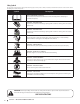
Safety Symbols This page depicts and describes safety symbols that may appear on this product. Read, understand, and follow all instructions on the machine before attempting to assemble and operate. Symbol Description READ THE OPERATOR’S MANUAL(S) Read, understand, and follow all instructions in the manual(s) before attempting to assemble and operate. WARNING— ROTATING BLADES Keep hands out of inlet and discharge openings while machine is running. There are rotating blades inside.
2 Assembly & Set-Up Thank You Thank you for purchasing this product. It was carefully engineered to provide excellent performance when properly operated and maintained. reserve the right to change product specifications, designs and equipment without notice and without incurring obligation. Please read this entire manual prior to operating the equipment. It instructs you how to safely and easily set up, operate and maintain your machine.
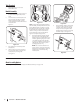
Tools Required • Adjustable Wrench or Socket Set • Needle Nose Pliers Handle Assembly 1. Cut cable ties securing chute control rod to lower handle (if applicable) and set aside. 2. On select units, loosen the top two lock nuts (a) securing the upper and lower handle and remove the two carriage screws (b) from the lower handle and set aside as shown in Figure 2-2.
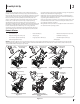
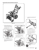
Standard Side Crank Chute Control Chute Directional Control Assembly Figure 2-6 1. 1. Position chute assembly over base. See Figure 2-7. Remove plastic cap (if present), flat washer (a) and hairpin clip (b) from end of chute directional control assembly. See Figure 2-9. (a) (b) Figure 2-7 2. Close flange keepers to secure chute assembly to chute base. Flange keepers will click into place when properly secure. See Figure 2-8.
U-Joint Side Crank Chute Control Chute Directional Control Assembly 1. Remove cotter pin from end of unattached chute directional control assembly. 2. Insert unattached chute directional control assembly into eye bolt on left side of handle assembly. See Figure 2-13. Figure 2-10 1. Position chute assembly over base. See Figure 2-11. (a) Figure 2-12 Figure 2-11 2. Close flange keepers to secure chute assembly to chute base. Flange keepers will click into place when properly secure. See Figure 2-12.
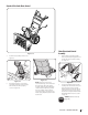
Overhead Chute Control (with Chute Control Rod) 4. Insert chute control rod into the support bracket on rear of the dash panel. See Figure 2-18. 5. Remove hairpin clip (a) from rear of chute control head. See Figure 2-19. 6. Insert chute control rod (b) into rear of chute control head. See Figure 2-19. Secure chute control rod to chute control assembly with hairpin clip (a) removed in Step 5. Figure 2-14 1.
Two & Four Way Chute Control Figure 2-20 (c) 1. Remove hairpin clip (a), wing nut (b) and hex screw (c) from chute control head and clevis pin (d) and bow-tie cotter pin (e) from chute support bracket. See Figure 2-21. (c) Chute Control Head (a) (d) (b) Chute Support Bracket Figure 2-23 4. Chute (e) Chute Base Figure 2-21 2. Insert chute control rod into chute control head. Push rod as far into chute control head as possible, keeping holes in rod pointing upward. See Figure 2-22. Figure 2-22 3.
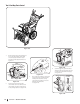
NOTE: Chute will not rotate without 7. squeezing trigger on joystick. 5. Rotate joystick to one o’clock position so that silver indicator arrow on pinion gear below control panel faces upward. See Figure 2-25. Push chute control rod toward control panel until hole in rod lines up with hole in chute control input closest to chute control head and insert hairpin clip (a) removed in Step 1. See Figure 2-27. (a) Figure 2-27 Figure 2-25 6.
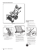
Overhead Chute Control (with Flex Shaft and Steel Chute) (a) (b) Figure 2-32 6. Insert hex end of flex shaft into chute control rod coupling under dash panel. See Figure 2-33. 7. Ensure speed selector is in fastest forward speed. 8. Remove cotter pin (a) and washer (b) from ferrule on end of shift rod. See Figure 2-34 inset. Figure 2-29 Figure 2-33 1. Remove lock nuts (a) and hex screws (b) from chute support bracket (this will require two wrenches). See Figure 2-30.
Electric Chute Control 5. Insert other end of chute control rod into coupler below handle panel. Make sure to line up flat end of rod and flat end of coupler. You may need to rotate rod around until these two surfaces line up. See Figure 2-40 inset. Figure 2-40 6. Push chute control rod toward the control panel until hole in rod lines up with middle hole in chute control input and insert cotter pin (a) removed in Step 1. See Figure 2-41. (a) Figure 2-35 1.
Set-Up Drift Cutters (If Equipped) Shear Pins Storage (If Equipped) The drift cutters are mounted inverted at the factory for shipping purposes. On select units, holes are provided in the rear of the handle panel for shear pin (a) and bow-tie cotter pin (b) storage as shown in Figure 2-42. If not provided, make sure to store them in a safe place until needed. Standard 1. Remove two screws (a) and lock nuts (b) that secure each drift cutter, and remove them from the sides of auger housing.
Skid Shoes Auger Control Lever The snow thrower skid shoes are adjusted at the factory set roughly 1/8” below the shave plate. Adjust them downward, if desired, prior to operating the snow thrower. WARNING! Prior to operating your unit, carefully read and follow all instructions below. Perform all adjustments to verify your equipment is operating safely and properly.
3 Controls & Operation Shift Lever Drive Control Lever Auger Control Lever Standard Chute Directional Control † Chute Assembly LED Light Bar † Clean Out Tool Augers Drift Cutters † U-Joint Chute Directional Control † Auger Housing Skid Shoe Overhead Chute Directional Control † Shift Lever Heated Grips † 4-Way/2-Way Chute Directional Control Joystiick † Shift Rod Manual Chute Directional Control † Electric Chute Directional Control Joystick † Headlight † Two-Way Chute-Pitch Control™ † Flex
Snow thrower controls and features are described below and illustrated in Figure 3-1. NOTE: This Operator’s Manual covers several models. Snow thrower features may vary by model. Not all features in this manual are applicable to all snow thrower models and the snow thrower depicted may differ from yours. Shift Lever The shift lever is located on the handle panel and is used to determine ground speed and direction of travel.
NOTE: Always release drive control lever before changing speeds. Failure to do so will result in increased wear on your machine’s drive system. Steering Trigger Controls (If Equipped) The left and right wheel steering trigger controls are located on the underside of the handles. Refer to Figure 3-6. 4-Way Chute Directional Control Joystick (If Equipped) • To change the direction in which snow is thrown, move the joystick to the right or to the left.
4. Grasp indented portion of chute control rod and manually rotate chute assembly to the right or to the left. See Figure 3-12. Starting and Stopping the Engine IMPORTANT: On 3-stage units, there is an additional shear pin in the rear accelerator. WARNING! Always keep hands and feet clear of moving parts. Do not use a pressurized starting fluid. Vapors are flammable. CAUTION: NEVER replace the auger shear pins with anything other than OEM Part No. 738-04124A replacement shear pins.
4 Service WARNING! Before servicing, repairing or inspecting the snow thrower, disengage the auger control lever. Stop the engine and remove the safety key to prevent unintended starting. (a) (a) Maintenance Engine (a) Refer to Engine Operator’s Manual. (a) Tire Pressure Refer to Assembly & Set-up section (page 14) for information regarding tire pressure.
4. (a) 5. (a) (b) (a) Rotate ferrule up or down on shift rod as necessary until it lines up with upper hole in shift lever. Refer to Figure 4-7 inset. Insert the ferrule into the upper hole and secure with the washer and cotter pin. If any of the above tests failed, the drive cable is in need of adjustment. Proceed as follows: 1. Shut OFF engine. Refer to the Engine Operator’s Manual. 2. Loosen lower hex screw (a) on drive cable bracket. See Figure 4-10.
Chute Control Rod (Two Way & Four Way Chute Control) (If Equipped) 2. To adjust chute control rod for increased engagement into the handle panel control, proceed as follows: 1. Remove hairpin clip (a) from hole closest to chute assembly on chute rotation assembly. 2. Pull out chute control rod until hole in it lines up with second hole in chute rotation assembly. See Figure 4-12.
10. NOTE: Not all friction wheels are serviceable. After replacing auger belt, perform Auger Control test in Assembly & Set-Up section (page 15). If this is the case, simply replace friction wheel assembly. 1. Drive Belt NOTE: See your authorized service dealer to Remove four screws (a) which secure friction wheel’s side plates together. See Figure 4-23. have drive belt replaced or contact Customer Support.
5 Troubleshooting Problem Engine fails to start Remedy 1. Choke not in CHOKE position. 1. Move choke to CHOKE position. 2. Spark plug wire disconnected. 2. Connect wire to spark plug. 3. Fuel tank empty or stale fuel. 3. Fill tank with clean, fresh fuel. 4. Engine not primed. 4. Prime engine as instructed in Engine Manual. 5. Faulty spark plug. 5. Clean, adjust gap or replace. 6. Safety key not in switch. 6. Insert safety key fully into switch. 7.