Safe Operation Practices • Set-Up • Operation • Service • Troubleshooting Operator’s Manual Snow Blower 2-Stage and 3-Stage (300, 500, 600 & 800 Series) Table of Contents Safe Operation Practices......................................... 2 Product Care........................................................... 22 Assembly & Set-Up................................................... 5 Parts/Warranty............... See Separate Supplement Controls & Operation..............................................
1 Important Safe Operation Practices WARNING! This symbol points out important safety instructions which, if not followed, could endanger the personal safety and/or property of yourself and others. Read and follow all instructions in this manual before attempting to operate the equipment. Failure to comply with these instructions may result in personal injury. When you see this symbol.
6. Do not operate machine while under the influence of alcohol or drugs. 7. Muffler and engine become hot and can cause a burn. Do not touch. Keep children away. 8. Exercise extreme caution when operating on or crossing gravel surfaces. Stay alert for hidden hazards or traffic. 9. Exercise caution when changing direction and while operating on slopes. Do not operate on steep slopes. 10. Plan your snow-throwing pattern to avoid discharge towards windows, walls, cars etc.
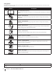
Safety Symbols This page depicts and describes safety symbols that may appear on this product. Read, understand, and follow all instructions on the machine before attempting to assemble and operate. Symbol Description READ THE OPERATOR’S MANUAL(S) Read, understand, and follow all instructions in the manual(s) before attempting to assemble and operate. WARNING— ROTATING BLADES Keep hands out of inlet and discharge openings while machine is running. There are rotating blades inside.
2 Assembly & Set-Up Thank You Thank you for purchasing this product. It was carefully engineered to provide excellent performance when properly operated and maintained. Please read this entire manual prior to operating the equipment. It instructs you how to safely and easily set up, operate and maintain your machine. Please be sure that you, and any other persons who will operate the machine, carefully follow the recommended safety practices at all times.
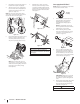
3. Place shift lever in Forward-6 position or fastest forward speed (if equipped). 4. Observe lower rear area of equipment to be sure both cables (if equipped) are aligned and seated properly in roller guides. See Figure 2-3. 6. Attach the two carriage screws (b) and nuts (a) removed in Step 2. Finish securing the handle by tightening the top two nuts (c) loosened in Step 2. See Figure 2-5 or Figure 2-6 for units with side supports.
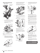
11. Insert a carriage screw (a) from the outside through a handle tab (b), the upper (c) and lower handles (d), a saddle washer (e) and into the wing knob (f). Repeat on the other side. Tighten the wing knobs (f) on each side of the handle. Refer to Figure 2-9. (c) (d) (c) (a) NOTE: The auger cable (a) routes down the left lower handle and the drive cable (b) is routed across the top of the lower handle and down the right side of the lower handle. See Figure 2-10.
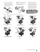
Standard Side Crank Chute Control 2. Close flange keepers to secure chute assembly to chute base. Flange keepers will click into place when properly secured. See Figure 2-14. 3. Remove plastic cap (if present), flat washer (a) and hairpin clip (b) from end of chute directional control assembly. See Figure 2-15. Chute Assembly Standard Side Crank Rod (a) (b) Figure 2-14 NOTE: Ensure the lower chute is secured to the flange on the chute base.
Overhead Chute Control (w/ Chute Control Rod) 2. Chute Assembly Place chute assembly onto chute base and secure chute control head to chute support bracket with clevis pin (c) and cotter pin (d) removed in Step 1. See Figure 2-18. 5. Remove hairpin clip (a) from rear of chute control head. See Figure 2-21. (a) (c) Overhead Chute Control Rod (b) (d) Figure 2-21 6. Figure 2-18 3. Finish securing chute control head to chute support bracket with wing nut (a) and hex screw (b) removed in Step 1.
2-Way & 4-Way Chute Control 3. Chute Assembly Chute Control Rod Place chute onto chute base and ensure chute control rod is positioned under handle panel. Install hex screw (c) removed in Step 1, but do not secure with wing nut at this time. See Figure 2-25. 6. Insert chute control rod into pinion gear below joystick. Make sure to line up hole in rod with arrow on pinion gear. See Figure 2-28. (c) Figure 2-28 NOTE: Chute control rod will fit snug into pinion gear.
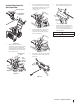
Overhead Chute Control (w/ Flex Shaft & Steel Chute) NOTE: For smoothest operation, cables should all be to the left of the chute directional control rod. 4. Chute Assembly 8. Remove cotter pin (a) and washer (b) from ferrule on end of shift rod. See Figure 2-36 inset. Remove hairpin clip (a) from rear of chute control assembly. See Figure 2-33. Ferrule (a) (a) Flex Shaft (b) (b) Shift Rod Figure 2-36 9.
Electric Chute Control 2. Chute Assembly Insert round end of chute control rod into chute control head. Push rod as far into chute control head as possible, keeping holes in rod pointing upward. See Figure 2-40. Chute Control Rod or Manual Chute Control Rod 3. Figure 2-44 Place chute onto chute base and ensure chute control rod is positioned under handle panel. Secure chute control head to chute support bracket with clevis pin (d) and bow-tie cotter pin (e) removed in Step 1. See Figure 2-41.
Set-Up Chute Control Cable Routing (If Equipped) For units equipped with 2-way or 4-way chute control joystick, electric chute control and/or chute-pitch controls, ensure control cables are routed properly. Shear Pins Storage (If Equipped) Tool-less On select units, holes are provided in the rear of the handle panel for shear pin (a) and bowtie cotter pin (b) storage as shown in Figure 2-47. If not provided, make sure to store them in a safe place until needed. 1.
Chute Clean-Out Tool Adjustments The chute clean-out tool is fastened to the top of the auger housing with a mounting clip. See Figure 2-51. Chute Assembly Skid Shoes NOTE: For models with 2-Way/4-Way or Electric Chute Directional Control and/or models with chute-pitch controls see Controls and Operation on page 19-20. On units with manual chute tilt, including E-Z Chute™, the distance snow is thrown can be adjusted by changing angle of chute assembly. To do so: 1.
Shave Plate 3. NOTE: This procedure applies to units equipped with adjustable shave plates only. To adjust the shave plate: 1. Allow engine to run until it is out of fuel. Do not attempt to pour fuel from the engine. 2. Carefully pivot unit up and forward so that it rests on auger housing. 3. Loosen rear skid shoe bolts (a) on both sides of auger housing and remove carriage bolts (b) and hex nuts (c) which attach shave plate (d) to the bottom of the auger housing. See Figure 2-55. 4.
Shift Rod (If Equipped) If full range of speeds (forward and reverse) cannot be achieved, adjust shift rod as follows: 1. Place shift lever in fastest forward speed position. 2. Remove cotter pin (a) and washer (b) from adjustment ferrule on shift rod and pull it out from shift lever. See Figure 2-59. (a) (b) Drive Control (Models with out Hydro Transmission) (If Equipped) Drive Control (Models with Hydro Transmission) (If Equipped) NOTE: Drive control on units with E-Z Chute™ is non-adjustable.
3 Controls & Operation Auger Control Lever* *If Equipped Drive Control Lever* Shift Lever* LED Light Bar* Chute Assembly Clean Out Tool Drift Cutters* Standard Chute Directional Control* Auger Housing Augers Skid Shoe Shift Lever Overhead Chute Directional Control* Heated Grips* 4-Way/2-Way Chute Directional Control Joystick* Heated Grip Switch* Headlight* Flex Shaft Chute Directional Control* Overhead Chute Directional Control* Chute Control Rod* Heated Grip Switch* Shift Lever Two-Way In
Snow thrower controls and features are described below and illustrated in Figure 3-1. NOTE: This Operator’s Manual covers several models. Snow thrower features may vary by model. Not all features in this manual are applicable to all snow thrower models and the snow thrower depicted may differ from yours. NOTE: All references to the left or right side of the snow thrower are from the operator’s position. Any exceptions will be noted.
Drive Control Lever/Auger Clutch Lock* (If Equipped) Steering Trigger Controls (If Equipped) 2-Way Chute Directional Control Joystick (If Equipped) The drive control lever is located on the right handle. Squeeze the control lever against the handle to engage the wheel drive. Release to stop. See Figure 3-5. The left and right wheel steering trigger controls are located on the underside of the handles. Refer to Figure 3-6.
Electric Chute Directional Control Joystick (If Equipped) The electric chute directional control joystick is located on the right side of the dash panel. Refer to Figure 3-10. • To change the direction in which snow is thrown, move the joystick to the right or to the left. • To change the angle/distance which snow is thrown, pivot the joystick forward or backward. 4. Grasp indented portion of chute control rod and manually rotate chute assembly to the right or to the left. See Figure 3-12.
Starting and Stopping the Engine WARNING! To Steer (If Equipped) With the drive control lever engaged, squeeze the right steering trigger control to turn right. Squeeze the left steering trigger control to turn left. Always keep hands and feet clear of moving parts. Do not use a pressurized starting fluid. Vapors are flammable. Refer to the Engine Operator’s Manual for instructions on starting and stopping the engine.
4 Product Care WARNING! Before servicing, repairing or inspecting the snow thrower, disengage the auger control lever. Stop the engine and remove the safety key to prevent unintended starting. Troubleshooting Engine Overheats 1. 1. 4. • 7. • • Faulty spark plug. 3. Replace drive belt. Contact an authorized Service Center. Friction wheel worn. • Replace friction wheel. Refer to Service section on page 26. Unit Plows Snow Instead of Blowing It 1.
Lubrication To remove skid shoes (Deluxe shown): 1. 2. Remove four carriage bolts (a) and hex flange nuts (b) and flat washers (c) which secure them to the unit. Wheels (a) (a) Rotate and reassemble new skid shoes with four carriage bolts (a) (two on each side) and hex flange nuts (b) and flat washers (c). Refer to Figure 4-1. At least once a season, remove both wheels. Clean and coat axles with a multipurpose automotive grease before reinstalling wheels.
Auger Shaft (b) At least once a season, remove shear pins (a) and cotter pins (b) from auger shaft(s). Spray lubricant inside shaft and around spacers and flange bearings found at either end of shaft(s). See Figure 4-6. (a) (a) (a) Figure 4-7 2. (a) (b) (a) (b) NOTE: Three Stage Augers Shown (b) Figure 4-9 2. Chute Control Rod (Two Way & Four Way Chute Control) (If Equipped) To adjust chute control rod for increased engagement into the handle panel control, proceed as follows: 1.
3. Roll auger belt off engine pulley. See Figure 4-12. Auger Belt Replacement (300 Series) 1. Allow the engine to run until it is out of fuel. Do not attempt to pour fuel from the engine. 2. Remove the safety key to prevent accidental starting. 3. Remove the self-tapping screw (a) shown in Figure 4-15, and press the plastic tabs (b) to release the belt cover (c). Pull the belt cover (c) up and out from around the engine and chute assembly. Set it aside and save. Figure 4-12 4.
5. Place the new drive belt (a) on the engine pulley. See Figure 4-19. 6. Tilt the transmission (b) forward and position the drive belt (c) onto the transmission pulley (d). See Figure 4-18. 7. Reconnect the spring (a) to the bolt on the engine frame and secure the transmission. Reinstall the flange lock nut. See Figure 4-18. 8. Reinstall the auger belt as instructed on page 25. 9. Reassemble the belt cover on the snow thrower 10. Reassemble the belt keeper to the housing.
Medidas de seguridad • Configuración • Funcionamiento • Servicio • Solución de problemas Manual del Operador Máquina quitanieves 2 etapas y 3 etapas (Serie 300, 500, 600 y 800) Índice Medidas de seguridad............................................. 2 Cuidado del producto............................................ 22 Montaje y configuración......................................... 5 Piezas/Garantía...... Consulte el suplemento que se Controles y funcionamiento..................................
1 Importantes medidas de seguridad ¡ADVERTENCIA! La presencia de este símbolo indica que se trata de instrucciones de seguridad importantes que debe respetar para evitar poner en riesgo su seguridad personal y/o material y la de los demás. Lea y siga todas las instrucciones de este manual antes de poner en funcionamiento este equipo. Si no respeta estas instrucciones puede provocar lesiones personales. Cuando vea este símbolo. TENGA EN CUENTA LA ADVERTENCIA.
6. No utilice la máquina bajo la influencia de alcohol o drogas. 7. El silenciador y el motor se calientan y pueden causar quemaduras. No los toque. Mantenga a los niños alejados. 8. Tenga mucho cuidado si cruza o usa la máquina en superficies con grava. Manténgase atento al tráfico y los riesgos ocultos. 9. Tenga cuidado cuando cambie de dirección o cuando opere la máquina en pendientes. No la utilice en pendientes pronunciadas. 10.
Símbolos de seguridad En esta página se presentan y describen los símbolos de seguridad que pueden aparecer en este producto. Lea, entienda y siga todas las instrucciones incluidas en la máquina antes de intentar armarla y hacerla funcionar. Símbolo Descripción LEA LOS MANUALES DEL OPERADOR Lea, entienda y siga todas las instrucciones incluidas en los manuales antes de intentar armarla y hacerla funcionar.
2 Montaje y configuración Gracias Gracias por comprar este producto. Se ha diseñado cuidadosamente para brindar excelente rendimiento si se opera y mantiene correctamente. especificaciones de los productos, diseños y equipos sin previo aviso y sin generar responsabilidad por obligaciones de ningún tipo. Por favor lea todo este manual antes de hacer funcionar el equipo. El manual le indica cómo configurar, operar y mantener la máquina de manera fácil y segura.
2. Unidades equipadas con canal E-Z Chute™ Afloje las dos tuercas superiores (a) que fijan la manija superior e inferior y extraiga los dos tornillos del carro (b) de la manija superiores y póngalos aparte como se muestra en la Figura 2-1 o Figura 2-2 para unidades con soportes laterales. NOTA: El canal E-Z Chute™ está identificado con una manija tipo lazo ubicada en la parte trasera del canal. E-Z Chute Conjunto del canal (b) (a) Figura 2-4 (a) (b) Figura 2-1 6.
5. Inserte un tornillo del carro (a) desde el exterior a través de una lengüeta de la barra de control (b), las barras de control superior (c) e inferior (d), una arandela cóncava (e), y al interior de la perilla de aletas (f). Repita lo mismo en el otro lado. Ajuste las perillas de aletas (f) a cada lado de la barra de control. Consulte la Figura 2-9. (b) (d) (d) (b) 6.
Control de canal con manivela lateral estándar Conjunto del canal 2. Cierre los fijadores de brida para sujetar el conjunto del canal a la base del canal. Los fijadores de brida emiten un chasquido cuando están bien asegurados. Consulte Figura 2-14. 3. Quite la tapa plástica (si está puesta), la arandela plana (a) y el sujetador de horquilla (b) del extremo del conjunto del control direccional del canal. Consulte Figura 2-15.
Control de canal superior (con varilla de control de canal) 2. Conjunto del canal Varilla de control del canal superior Ubique el conjunto del canal sobre la base del mismo y sujete el cabezal de control del canal a la ménsula de soporte del canal mediante el pasador de horquilla (c) y el pasador de chaveta (d) que extrajo en el Paso 1. Consulte Figura 2-18. 5. Retire el sujetador de horquilla (a) de la parte posterior del cabezal de control del canal. Consulte Figura 2-21.
Control del canal de dos y cuatro direcciones Conjunto del canal 3. Varilla de control del canal Coloque el canal sobre la base del canal y asegúrese de que la varilla de control del canal se encuentre debajo del panel de la manija. Coloque el tornillo hexagonal (c) que extrajo en el Paso 1 pero no lo sujete con la tuerca de mariposa en este momento. Consulte Figura 2-25. (c) Figura 2-28 NOTA: La varilla de control del canal encajará justo en el engranaje del piñón.
Control de canal superior (con eje flexible y canal de acero) NOTA: Para lograr el mejor funcionamiento, todos los cables se deben dejar a la izquierda de la varilla de control direccional del canal. 7. Asegúrese de que el selector de velocidad esté en la velocidad más rápida de marcha adelante. 4. 8. Extraiga el pasador de chaveta (a) y la arandela (b) de la férula que está en el extremo de la varilla de cambio. Consulte el recuadro Figura 2-36.
Control eléctrico del canal 6. Conjunto del canal Varilla de control del canal o Varilla de control manual del canal (a) Figura 2-40 3. Coloque el canal sobre la base del canal y asegúrese de que la varilla de control del canal se encuentre debajo del panel de la manija. Sujete el cabezal de control del canal a la ménsula de soporte del canal con el pasador de horquilla (d) y el pasador de chaveta con unión curva (e) que extrajo en el Paso 1. Consulte Figura 2-41.
Configuración Enrutamiento de Cable de Control de Canal (si se incluyera) Para unidades equipadas con palanca de control de canal de 2 o 4 vías, control eléctrico de canal y/o controles de inclinación de canal, verifique que los cables estén correctamente tendidos.
Herramienta de limpieza del canal NOTA: Si tiene que usar la unidad sobre grava, mantenga las zapatas antideslizantes en la posición que permita lograr una separación máxima entre el piso y la placa de raspado. La herramienta de limpieza del canal viene sujeta de fábrica a la parte superior de la caja de la barrena con un pasador de ensamblado y un precinto. Corte el precinto antes de operar la unidad. Consulte Figura 2-51. Para ajustar las zapatas antideslizantes: 1. Figura 2-52 2.
Placa de raspado 3. NOTA: este procedimiento aplica únicamente a unidades equipadas con placas de raspado regulables. Para ajustar la placa de raspado: 1. Si hay combustible en el motor, deje el motor en marcha hasta que se acabe el combustible. No intente verter combustible del motor. 2. Gire con cuidado la unidad hacia arriba y hacia adelante de manera que quede apoyada sobre la caja de la barrena. 3.
Varilla de cambios (si viene equipada) Si no se puede lograr la gama completa de velocidades (marcha adelante y atrás), ajuste la varilla de cambios de la siguiente manera: 1. Coloque la palanca de cambios en la posición más rápida de marcha adelante. 2. Extraiga el pasador de chaveta (a) y la arandela (b) de la férula de ajuste de la varilla de cambios y extráigala de la palanca de cambios. Consulte la Figura 2-59. (a) (b) Figura 2-59 3.
3 Controles y funcionamienton Palanca de control de la barrena † Palanca de control de la transmisión † † si vienen equipados Palanca de control de la transmisión † Barra de luces LED † Conjunto del canal Control direccional del canal de junta universal † Herramienta de limpieza Cortadores de desplazamiento de nieve † Control direccional del canal estándar † Caja de la barrena Barrenas Zapata antideslizante Palanca de cambios Agarres térmicos † Palanca de control direccional del canal de 4/2 di
Los controles y las características de la máquina quitanieves se describen a continuación y se ilustran en la Figura 3-1. NOTA: Este manual de operación, corresponde a numerosos modelos. Las características técnicas de la máquina quitanieves pueden variar según los modelos. No todas las características en este manual se aplican a todos los modelos de máquina quitanieves y la máquina que se ilustra aquí puede diferir de la suya.
Palanca de control de la barrena La palanca de control de la barrena está ubicada en la manija izquierda. Apriete la palanca de control contra la manija para activar las barrenas y empezar a quitar nieve. Suéltela para que se detenga. Vea la Figura 3-4. CONTROL DE LA BARRENA Figura 3-4 IMPORTANTE: Consulte la Información de Control de la Barrena en la sección Montaje y Configuración antes de hacer funcionar la máquina quitanieve.
Palanca de control direccional del canal eléctrico (si está incluida) Control de inclinación del canal de dos direccione La palanca de control direccional del canal eléctrico está ubicada en el lado derecho del tablero de instrumentos. Consulte la Figura 3-10. • • Para cambiar la dirección en que se quita la nieve, mueva la palanca de control hacia la derecha o hacia la izquierda. Para cambiar el ángulo/la distancia en que se quita la nieve, gire la palanca de control hacia adelante o hacia atrás.
Procedimiento para engranar la transmisión 1. 2. Reemplazo de los pasadores de cuchilla Con el control del regulador en posición Fast (conejo), mueva la palanca de cambios a una de las seis posiciones de avance (F) o de las dos posiciones de marcha atrás (R) en el caso de unidades con 6 velocidades o a la posición deseada en el caso de unidades con transmisión hidrostática. Seleccione una velocidad adecuada a las condiciones de nieve presentes y con la cual se sienta cómodo.
4 Cuidado del producto ¡ADVERTENCIA! Antes de realizar tareas de mantenimiento, reparación o inspección en la máquina quitanieves, desengrane la palanca de control de la barrena. Pare el motor y retire la llave de seguridad para evitar el encendido accidental del motor. Solución de problemas El motor no arranca 1. Se ha desconectado el cable de bujía. • Conecte el cable a la bujía. 3. El depósito de combustible está vacío o el combustible se ha echado a perder. 6. 1.
Lubricación NOTA: Las zapatas antideslizantes de lujo (en determinados modelos) tienen dos bordes de desgaste. Cuando un lado se desgasta, se las puede rotar 180º para usar el otro borde. Para retirar las zapatas antideslizantes (se muestran las Deluxe): 2. 3. Gire y vuelva a montar las zapatas antideslizantes nuevas con los cuatro pernos de carro (a) (dos a cada lado) y las tuercas de brida hexagonales (b) y las arandelas planas (c). Consulte la Figura 4-1. (c) (a) (c) (b) Figura 4-1 3.
Eje de la barrena Al menos una vez por temporada, quite los pasadores de cuchilla (a) y los pasadores de chaveta (b) del eje de la barrena. Rocíe lubricante en el interior del eje y alrededor de los separadores y los cojinetes bridados que se encuentran en ambos extremos del eje. Consulte la Figura 4-6.
4. 5. 6. Gire con cuidado la unidad hacia arriba y hacia adelante de manera que quede apoyada sobre la caja de la barrena. Reemplazo de la correa de transmisión (Serie 300) (a) Saque la cubierta del marco desde debajo de la unidad, para lo que debe extraer los tornillos autorroscantes que la sujetan. Consulte la Figura 4-4. (c) 1. Extraiga la correa de la barrena como se indica en la página 25. 2. Quite el resorte que conecta la transmisión a un perno en el cuadro del motor. Vea la Figura 4-18.
Inspección de la rueda de fricción (Serie 500 orientable y Serie 600 de velocidad única y no orientable) Si está desmontando la rueda de fricción para reemplazar únicamente el anillo de goma, proceda como se indica a continuación: NOTA: No todas las ruedas de fricción se pueden reparar. Si ese es el caso, simplemente reemplace el conjunto de la rueda de fricción. 9.