
Full Product Manual


10 Section 2 — ASSembly & Set-Up
2-Way & 4-Way Chute Control
Chute Control
Rod
Chute Assembly
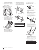
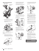
Figure 2-22
1. Remove hairpin clip (a), wing nut (b) and
hex screw (c) from chute control head
and clevis pin (d) and bow-tie cotter pin
(e) from chute support bracket.
See Figure 2-23.
(a)
(c)
Chute Control Head
Chute
Chute
Support
Bracket
Chute Base
(e)
(d)
(b)
Figure 2-23
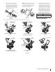
NOTE: For smoothest operation, cables should
all be to the left of the chute directional
control rod.
2. Insert chute control rod into chute
control head. Push rod as far into chute
control head as possible, keeping holes
in rod pointing upward. See Figure 2-24.
Figure 2-24
3. Place chute onto chute base and ensure
chute control rod is positioned under
handle panel. Install hex screw (c)
removed in Step 1, but do not secure with
wing nut at this time. See Figure 2-25.
(c)
Figure 2-25
4. Squeeze trigger on joystick and rotate
chute by hand to face forward. The holes
in chute control input will be facing up.
See Figure 2-26.
Chute Control Input
Top View
Joystick
Figure 2-26
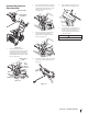
NOTE: Chute will not rotate without
squeezing trigger on joystick.
5. Rotate joystick to one o’clock position
so that indicator arrow on pinion gear
below control panel faces upward. See
Figure 2-27.
Figure 2-27
6. Insert chute control rod into pinion gear
below joystick. Make sure to line up hole
in rod with arrow on pinion gear. See
Figure 2-28.
Figure 2-28
NOTE: Chute control rod will fit snug
into pinion gear. Support rear of dash
panel with one hand while inserting rod
with your other hand to ensure rod is
inserted all the way into pinion gear.
NOTE: The hole in the chute directional
control rod is a reference for aligning
rod with indicator arrow on pinion gear,
and will be visible after rod has been
inserted.
7. Push chute control rod toward control
panel until hole in rod lines up with hole
in chute control input closest to chute
control head and insert hairpin clip (a)
removed in Step 1. See Figure 2-29.
(a)
Figure 2-29
NOTE: Second hole is used to achieve
further engagement of chute control
rod into pinion gear if required. Refer to
Product Care section for Chute Control
Rod adjustments.
8. Finish securing chute control head to
chute support bracket with wing nut (b),
clevis pin (d), and bow-tie cotter pin (e)
removed in Step 1.
STOP
Continue to Set-Up (page 13).