
Full Product Manual


5
Assembly & Set-Up
2
Thank you for purchasing this product. It was carefully engineered to
provide excellent performance when properly operated and maintained.
Please read this entire manual prior to operating the equipment. It
instructs you how to safely and easily set up, operate and maintain your
machine. Please be sure that you, and any other persons who will operate
the machine, carefully follow the recommended safety practices at all
times. Failure to do so could result in personal injury or property damage.
All information in this manual is relative to the most recent product
information available at the time of printing. Review this manual frequently
to familiarize yourself with the machine, its features and operation. Please
be aware that this Operator’s Manual may cover a range of product
specifications for various models. Characteristics and features discussed
and/or illustrated in this manual may not be applicable to all models. We
reserve the right to change product specifications, designs and equipment
without notice and without incurring obligation.
If applicable, the power testing information used to establish the power
rating of the engine equipped on this machine can be found at www.opei.
org or the engine manufacturer’s web site.
If you have any problems or questions concerning the machine, phone your
local authorized service dealer or contact us directly. We want to ensure
your complete satisfaction at all times.
Throughout this manual, all references to ri ght and left side of the machine
are observed from the operating position.
Thank You
Contents of Carton
• Snow Thrower (1) • Snow Thrower Operator’s Manual (1) • Skid Shoe Kit*
• Chute Assembly (1) • Engine Operator’s Manual (1) Short Carriage Screw (4)
• Chute Control Rod, Flex Shaft, or Side • Parts/Warranty Document (1) Flat Washer (4, if required)
Crank Rod Assembly* (1) • Handle Hardware Flange Lock Nut (4)
• Replacement Auger Shear Pins (2) Long Carriage Screw* (2)
• Safety Key (2) Flange Lock Nut* (2) * If Equipped
NOTE: This Operator’s Manual covers several models. Features may vary by model. Not all features in this manual are applicable to all models and the
model depicted may differ from yours. Refer to Figure 2-1 which shows the different versions and match the contents of carton (chute and directional
control rod/flex shaft) to identify your specific unit.
Overview
• Remove packaging materials from snow
thrower.
• Rotate Handle into the upright position.
Refer to Handle Assembly.
• Install the chute. Refer to Chute
Assembly Options.
• Complete snow thrower assembly
according to model and equipment.
Refer to Set-up.
• If necessary make adjustments to ensure
proper snow thrower operation. Refer to
Adjustments.
• Add fuel and oil. Refer to the Engine
Operator’s Manual shipped with snow
thrower.
Tools Required
• Adjustable Wrench or Socket Set
• Needle Nose Pliers
Handle Assembly
1. Perform one of the following:
• All Units without E-Z Chute™ (units
equipped with Chute Controls) -
Proceed to All Units Without E-Z Chute
on page 5.
• All Units Equipped with E-Z Chute™
- Proceed to Units Equipped with E-Z
Chute™ on page 6.
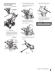
All Units Without E-Z Chute™
1. Cut cable ties securing chute control rod
or upper handle to the lower handle (if
applicable), set aside the chute control
rod (if applicable) and remove the wrap
around the handles (if applicable).
NOTE: Do not cut the cable tie securing
the cables to the engine for units
equipped.
NOTE: On units with Overhead Chute
Control (with Flex Shaft), Four-Way Chute
Control, and Electric Chute Control
cut cable ties securing flex shaft to the
lower handle and set the flex shaft aside.
Remove rubber bands securing cables to
carriage screws and cut cable tie securing
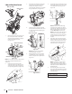
shift rod to lower handle. Refer to Figure
2-11 to help identify your unit.
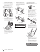
2. Loosen the top two nuts (a) securing the
upper and lower handle and remove the
two carriage screws (b) from the upper
handle and set aside as shown in Figure
2-1 or Figure 2-2 for units with side
supports.
(a)
(a)
(b)
(b)
Figure 2-1
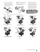
(a)
(a)
(b)
(b)
Figure 2-2