
Full Product Manual


6 Section 2 — ASSembly & Set-Up
Units equipped with E-Z Chute™
NOTE: E-Z Chute is identified by a loop handle
located on the back of the chute.
E-Z Chute
Assembly
7. Remove cable tie (if present) securing
upper handle to lower handle for
shipping purposes. Remove all
protective plastic wrapping from
handles.
NOTE: Be careful NOT to remove the
two loosely fitted cable ties that will be
utilized later to secure cables.
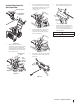
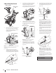
8. Remove the wing knob (a), saddle
washer (b), handle tab (c) and carriage
screw (d) on each side of the lower
handle. See Figure 2-7.
(c)
(b)
(a)
(d)
Figure 2-7
9. Slide one of the loosely fitted cable
ties (a) from the right side of the lower
handle (b) up to the cross member of
the lower handle (c). Leave the second
cable tie in place on the right side of the
lower handle (b). See Figure 2-8.
(b)
(d)
(c)
(a)
Figure 2-8
IMPORTANT: It will be necessary to lift
the upper handle (d) while sliding up
this cable tie to prevent damage to the
cable.
10. Lift the upper handle (d) up and position
it over the lower handle (b), aligning
the holes where the wing knobs were
removed. See Figure 2-8.
CAUTION
Be careful not to bend or kink the cables.
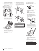
3. Place shift lever in Forward-6 position or
fastest forward speed (if equipped).
4. Observe lower rear area of equipment
to be sure both cables (if equipped) are
aligned and seated properly in roller
guides. See Figure 2-3.
NOTE: On select units, chute-pitch control
cables will be routed under the engine on the
left side and will not use roller guides.
Figure 2-3
5. Pivot handle upward and align the lower
handle. See Figure 2-4. Remove and
discard any rubber bands, if present.
They are for packaging purposes only.
Figure 2-4
NOTE: On select units with steel rod
speed selectors, you may need to lower
shift rod to the side slightly to maneuver
handle panel over it when pivoting
handle upward.
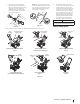
6. Attach the two carriage screws (b)
and nuts (a) removed in Step 2. Finish
securing the handle by tightening the
top two nuts (c) loosened in Step 2. See
Figure 2-5 or Figure 2-6 for units with
side supports.
(c)
(c)
(b)
(b)
(a)
(a)
Figure 2-5
(c)
(c)
(a)
(a)
(b)
(b)
Figure 2-6
STOP
Refer to “Figure 2-11” on page 7 to identify your
applicable chute style and continue to Chute Assembly
Options (page 7).