
Full Product Manual


8 Section 2 — ASSembly & Set-Up
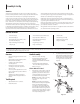
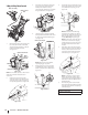
Standard Side Crank Chute
Control
Standard Side Crank
Rod
Chute Assembly
Figure 2-12
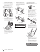
1. Position chute assembly over base.
See Figure 2-13.
Figure 2-13
2. Close flange keepers to secure chute
assembly to chute base. Flange keepers
will click into place when properly
secured. See Figure 2-14.
Figure 2-14
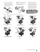
NOTE: Ensure the lower chute is secured to
the flange on the chute base. The lower edge
of the chute keeper should be positioned
below the flange on the chute base after being
clicked into place.
If flange keepers will not
easily click into place, use palm of your hand to
apply swift, firm pressure to the back of each.
3. Remove plastic cap (if present), flat
washer (a) and hairpin clip (b) from end
of chute directional control assembly.
See Figure 2-15.
(b)
(a)
Figure 2-15
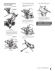
4. Insert end of chute directional control
assembly into lower bracket and secure
chute directional control assembly
with flat washer (a) and hairpin clip (b)
removed in Step 1. If necessary, lower
bracket can be adjusted. Refer to Chute
Bracket Adjustment in Service section
on page 24.
STOP
Continue to Set-Up (page 13).