
Use and Care Manual


13
ASSEMBLY
Set-Up
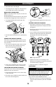
CHUTE CONTROL CABLE ROUTING IF EQUIPPED
For models equipped with 2-way or 4-way chute controls,
electric chute control and/or chute-pitch controls, ensure control
cables are routed properly.
Chute control cables are routed through a single wire guide (a) on
top of the engine and/or through two wire guides (b) located on
the front and left side of the engine (Figure 35).
NOTE: On models equipped with a cable tie securing the cables to
the rear of the gas tank, pull the cables toward the chute and pull
the cable tie snug to secure the cables in place.
NOTE: For smoothest operation, cables should all be to the left of
the chute control rod (c).
NOTE: The number of cables routed through the wire guides will
vary depending on model.
1. Locate cable guide(s) and perform the following:
• Top Mounted Wire Guide (a) - Check that all cables are
properly routed through cable guide on top of engine
(Figure 35).
• Front and Side Mounted Wire Guides (b) - Check that all
cables are properly routed through the wire guide below the
left side of the engine and the wire guide below the chute
control head (Figure 35).
a
c
c
b
Figure 35
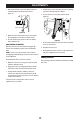
SHEAR PINS STORAGE IF EQUIPPED
On select models, holes are provided in the rear of the handle
panel for shear pin (a) and bow-tie cotter pin (b) storage as
shown in Figure 36. If not provided, make sure to store them in a
safe place until needed.
a
a
a
b
b
b
b
a
Figure 36
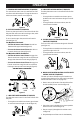
DRIFT CUTTERS IF EQUIPPED
The drift cutters are mounted inverted at the factory for shipping
purposes.
Non-Adjustable
1. Remove two carriage bolts (a) and lock nuts (b) that secure
each drift cutter, and remove them from the sides of auger
housing (Figure 37).
a
b
Figure 37
2. Turn the drift cutters around and position them as shown in
Figure 37 to the outside of the auger housing.
3. Attach drift cutters with carriage bolts (a) and lock nuts (b)
removed in Step 1.
Tool-less
1. Remove two carriage bolts (a) and wing knob (b) that secure
each drift cutter, and remove them from the sides of auger
housing (Figure 38).