
Use and Care Manual


15
ADJUSTMENTS
2. Slide the drift cutters to desired height.
3. Securely tighten the two carriage bolts and wing knob that
secure each drift cutter to the sides of auger housing.
MANUAL CHUTE PITCH ADJUSTMENT
NOTE: For models without manual chute pitch, see Controls and
Operation on page 20-21.
On models with manual chute pitch, the distance snow is thrown
can be adjusted by changing angle of chute assembly. To do so:
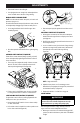
1. Loosen wing knob found on left side of the upper chute
assembly (Figure 43).
Figure 43
2. Pivot chute upward or downward before re-tightening wing
knob.
OVERHEAD CHUTE CONTROL IF EQUIPPED
If chute fails to remain stationary during operation, preload of
chute can be adjusted by tightening hex nut found on front of
chute control head.
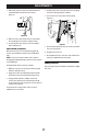
1. To increase preload, tighten hex nut (a) clockwise in ¼ turn
intervals. The chute control rod (b) will need to be held
stationary when tightening the nut (Figure 44).
a
b
Figure 44
2. If chute control rod is difficult to turn, decrease preload by
loosening hex nut counter-clockwise in ¼ turn intervals.
2WAY OR 4WAY CHUTE CONTROL IF EQUIPPED
To adjust chute control rod for increased engagement into the
handle panel control, proceed as follows:
1. Remove hairpin clip (a) from hole closest to chute assembly
on chute control head.
2. Pull out chute control rod until hole in it lines up with second
hole in chute control head (Figure 45).
a
Figure 45
3. Reinsert hairpin clip (a) through this hole and chute control
rod.
ADJUSTABLE SHAVE PLATE IF EQUIPPED
1. Allow engine to run until it is out of fuel. Do not attempt to
drain fuel from the engine. Remove safety key or disconnect
spark plug wire.
2. Carefully pivot snow blower up and forward so that it rests on
front of auger housing.
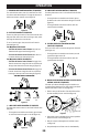
3. Loosen rear skid shoe nuts (a) on both sides of auger housing
and remove carriage bolts (b) and hex nuts (c) which attach
shave plate (d) to the bottom of the auger housing
(Figure 46).
d
c
c
c c
b
b
b b
a
a
Figure 46
NOTE: 3-Stage model shown.
4. Adjust the shave plate to one of 2 mounting positions.
Reinstall and securely tighten all carriage bolts, nuts and skid
shoe hardware from Step 3 (Figure 46).
5. Readjust the skid shoes. See Skid Shoes on page 15.
AUGER CONTROL
WARNING
Prior to operating, carefully read and follow all
instructions below. Perform all adjustments to verify
your snow blower is operating safely and properly.
Refer to Auger Control Lever on page 19 for the location of
auger control lever and check adjustment as follows:
1. When auger control lever is released and in disengaged “UP”
position, the cable should have very little slack. It should NOT
be tight.