
Use and Care Manual


19
OPERATION
FEATURES
Snow blower controls and features are described below and may
be illustrated in Figure 52.
NOTE: This Operator’s Manual covers several models. Snow
blower features may vary by model. Not all features in this
manual are applicable to all snow blower models and the snow
blower depicted may differ from yours.
NOTE: All references to the left or right side of the snow blower
are from the operator’s position. Any exceptions will be noted.
A. ENGINE CONTROLS
Refer to your Engine Operator’s Manual for location and
description of engine controls pertaining to your engine.
B. CHUTE ASSEMBLY
Snow gathered into the auger and impeller housings is
discharged out the chute assembly.
C. SKID SHOES
Skid shoes provide the proper clearance of the shave plate for the
surface conditions and the snow to be cleared. Adjust upward for
hard-packed snow. Adjust downward when operating on gravel
or crushed rock surfaces. See Skid Shoe Adjustment section on
page 14.
D. AUGERS
When engaged, the augers rotate and gather snow into the
auger and impeller housings.
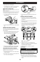
E. DRIVE CONTROL LEVER/AUGER CLUTCH LOCK*
(IF EQUIPPED)
The drive control lever is located on the right handle. Squeeze the
control lever down against the handle to engage the track drive.
Release to stop (Figure 53).
Figure 53
*On select models, the drive control lever also locks the auger
control lever so that you can operate the chute control without
interrupting the snow blowing process. When both the auger
and drive levers are engaged at any time, the operator can
release the auger control lever (on the left handle) and the
augers will remain engaged. Release both control levers to stop
augers and track drive.
NOTE: Always release drive control lever before changing speeds.
Failure to do so will result in increased wear on your machine’s
drive system.
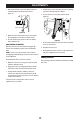
F. AUGER CONTROL LEVER
The auger control lever down is located on the left handle.
Squeeze the control lever against the handle to engage the
augers and start snow blowing action. Release to stop
(Figure 54).
Figure 54
IMPORTANT: Refer to the Auger Control information in the
Assembly & Set-Up section prior to operating your snow blower.
Read and follow all instructions carefully and perform all
adjustments to verify your snow blower is operating safely and
properly.
G. SHIFT LEVER (6-SPEED TRANSMISSION) (IF EQUIPPED)
The shift lever is located on the handle panel and is used to
determine ground speed and direction of travel.
• Forward
There are six forward (F) speeds. Position
one (1) is the slowest and position six (6) is the fastest.
• Reverse
There are two reverse (R) speeds. Position one (1) is the
slowest and position two (2) is the fastest.
H. HEADLIGHT (SINGLE OR DUAL) (IF EQUIPPED)
The headlight(s) located on the front of the handle panel is/are
automatically turned ON when the engine is started.
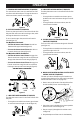
I. STEERING TRIGGER CONTROLS (IF EQUIPPED)
The left and right track steering trigger controls are located on
the underside of the handles (Figure 55).
Figure 55
• Squeeze the right trigger control to turn right.
• Squeeze the left trigger control to turn left.
CAUTION
Operate the snow blower in open areas until you are
familiar with these controls.