
Use and Care Manual

Assembly & Set-Up
3
7
Assembly
Remove all loose parts before assembling.
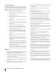
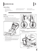
Handle Assembly
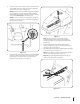
1. Place the shift lever in the Forward-6 position
2. Obser ve the lower rear area o f the snow thrower to be sure both
cables are aligned with roller guides before pivoting the
handle upward. Pivot the handle upward. See Figure 3-1.
Figure 3-1
NOTE: Make certain the cables are seated properly in the
roller guides. See Figure 3-2.
3. Secure the handle by tightening the plastic knob located
on both the left and right sides of the handle. Remove
and discard any rubber bands, if present. They are for
packaging purposes only.
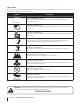
Contents of Carton
• One Snow Thrower • Two Replacement Auger Shear Pins • One Chute Assembly
• One Chute Control Rod • One Product Registration Card • One Engine Operator’s Manual
• One Snow Thrower Operator’s
Manual
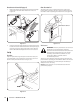
Figure 3-2
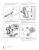
Chute Assembly
1. Remove hairp in clip, wing nut and he x screw from chute control
head and clevis pin and bow-tie cotter pin from chute
support bracket. See Figure 3-3.
Chute Control Head
Chute
Chute Support
Bracket
Chute Base
Figure 3-3