Illustrated Parts Manual Two Stage Snow Thrower — 945 SWE CUB CADET LLC, P.O. BOX 361131 CLEVELAND, OHIO 44136-0019 Printed In USA Form No.
To The Owner Thank You Thank you for purchasing a Cub Cadet Snow Thrower. It was carefully engineered to provide excellent performance when properly operated and maintained. All information in this manual is relative to the most recent product information available at the time of printing. Please be aware that this Illustrated Part’s Manual may cover a range of product specifications for various models. Components listed and/or illustrated in this manual may not be applicable to all models.
This page left intentionally blank.
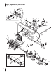
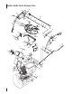
Augers, Auger Housing, and Gearbox 14 70 10 30 1 24 26 21 26 19 21 11 8 18 4 71 16 3 17 46 23 9 22 11 6 20 29 7 33 11 31 35 17 11 72 37 39 12 2 36 34 7 49 11 74 73 6 40 43 15 5 13 25 48 45 38 41 75 12 44 51 43 62 64 52 68 63 66 47 67 61 51 55 65 67 4 69 56 58 57 63 64 59 60 69 51 68 53 54 50 14 32 27 51 28 42 50
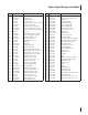
Augers, Auger Housing, and Gearbox Ref. Part Number Description Ref. Part Number 1. 2. 3. 4. 5. 6. 7. 8. 9. 10. 11. 12. 13. 14. 15. 16. 17. 18. 19. 20. 21. 22. 23. 24. 25. 26. 27. 28. 29. 30. 31. 32. 33. 34. 35. 36. 37. 38.
Handles, Handle Panel & Discharge Chute 24 37 30 29 48 44 20 32 45 40 22 36 31 25 33 72 31 27 41 39 32 28 34 77 21 38 50 12 46 42 19 4 43 73 49 70 13 55 78 16 79 81 62 80 74 17 71 53 62 68 76 8 10 6 12 15 14 9 6 6 52 69 67 59 75 65 60 66 11 65 56 54 58 63 61 57 7 18 3 26 47 5 2 37 1 22 35 51 11 23 64
Handles, Handle Panel & Discharge Chute Ref. Part Number 1. 2. 3. 4. 5. 6. 7. 8. 9. 10. 11. 12. 13. 14. 15. 16. 17. 18. 19. 20. 21. 22. 23. 24. 25. 26. 27. 28. 29. 30. 31. 32. 33. 34. 35. 36. 37. 38. 39. 40. 41.
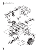
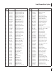
Snow Thrower Drive System 100 86 90 97 81 98 22 85 76 91 73 88 79 87 82 75 92 77 93 84 99 74 83 95 96 94 80 101 53 65 78 104 9 109 35 50 22 72 56 37 32 4 26 57 69 27 63 64 26 51 44 11 22 33 55 6 58 54 62 21 25 5 11 33 16 28 59 60 2 18 68 8 19 19 61 45 89 108 70 7 36 3 16 37 24 41 57 49 12 1 34 17 31 31 52 66 47 29 106 15 107 53 54 62 105 12 40 20 51 39 13 67 14 103 46 30 48 38 50 31 43 71 10 12 23 65 16 42 8 102
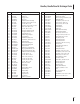
Snow Thrower Drive System Ref. No. Part No. Description Ref. No. Part No. Description 1. 05244B Housing, Bearing 40. 936-0864 Wash, .375 x .812 x .060 2. 618-0279P Dogg, Steering Drive, LH 41. 936-0329 Washer, Lock, 1/4 3. 618-0280P Dogg, Steering Drive, RH 42. 711-04615 Pin, Clevis 4. 918-0282E Shaft Assembly, Steering 43. 914-0149B Pin, Internal Cotter 5. 918-04178 6. Assembly, Friction Wheel 44.
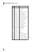
Snow Thrower Drive System (Continued) Ref. No. Part No. 81. 710-0347 Screw, Hex Cap, 3/8-16 x 1.75 82. 714-0118 Key, Square, 1/4 x 1.5 83. 926-04012 Nut, Push 84. 931-2531 Cover, Belt 85. 732-04308A Torsion Spring, .850 dia. x .333 lg. 86. 936-0119 Washer, Lock, 5/16 87. 736-0247 Washer, Flat, .406 x 1.25 88. 736-3092 Washer, Flat, .265 x 1.0 x .030 89. 712-04064 Flange Lock Nut 1/4-20 90. 748-04112B Shldr. Spacer, .3175 x .500 x .094 91. 750-04571 Shldr. Spacer, .260 x .
Labels 777D15123 777X43688 777D15045 777I22340 777D15086 777S32636 AVOID INJURY FROM ROTATING AUGER KEEP HANDS, FEET AND CLOTHING AWAY. DANGER 777S32280 777D15110 777I22341 DANGER 1. KEEP AWAY FROM ROTATING IMPELLER AND AUGER. CONTACT WITH IMPELLER OR AUGER CAN AMPUTATE HANDS AND FEET. 2. USE CLEAN-OUT TOOL TO UNCLOG DISCHARGE CHUTE. 3. DISENGAGE CLUTCH LEVERS, STOP ENGINE, AND REMAIN BEHIND HANDLES UNTIL ALL MOVING PARTS HAVE STOPPED BEFORE UNCLOGGING OR SERVICING MACHINE. 4.
490-SUB Muffler & Controls 1 2 3 5 4 3 3 8 3 10 7 10 3 11 3 9 10 3 3 12 13 39 38 14 15 Ref. 1 710-04915 Description Ref.
490-SUB Carburetor 129 130 131 132 133 136 134 135 137 147 - Carburetor Rebuild Kit Ref. Part Number Description Ref.
490-SUB Crankcase 40 76 75 42 41 44 71 74 70 68 66 68 66 66 43 69 66 73 64 77 61 62 65 141 140 81 67 66 48 61 62 56 50 143 57 59 54 51 50 49 52 53 14 78 55 58 60 42 79 80 144 - Gasket Kit - Complete 145 - Gasket Kit - External 146 - Complete Engine
490-SUB Crankcase Ref. Part Number Description Ref.
490-SUB Fuel Tank & Mounting 16 17 18 19 18 19 21 18 18 20 20 25 27 26 22 25 26 29 34 32 33 30 35 37 23 29 26 29 16 26 Part Number Description Ref. 25 24 29 36 Ref.
490-SUB Starter Assembly & Blower Housing 87 83 84 86 85 82 83 46 45 47 45 47 93 85 90 88 95 92 93 91 96 89 97 98 93 97 93 Ref. Part Number Description Ref. Part Number 98 97 98 Description 45 710-04965 Screw M4 X 55 89 951-11313 Cooling Fan 46 951-11196 Electric Starter 90 951-11314 Starter Cup 47 710-04967 Bolt M8×55 91 712-04220 Flywheel Nut, M14×1.
490-SUB Cylinder Head 106 108 105 105 109 115 114 113 116 142 114 115 125 100 101 112 116 107 123 110 111 122 121 104 113 120 110 102 103 119 110 117 124 123 122 120 119 121 127 128 118 123 123 123 126b 126a 144 - Gasket Kit - Complete 145 - Gasket Kit - External 146 - Complete Engine 18 128
490-SUB Cylinder Head Ref. Part Number Ref. Part Number 100 951-11337 101 951-11337 Valve Kit 116 951-12081 Exhaust Lash Cap Valve Kit 117 951-11965 Push Rod Guide 102 951-11962 Tappet 118 951-11981 Rocker Arm Assembly 103 951-11335 Push Rod Kit 119 710-04962 Bolt, Pivot 104 951-12592 Cylinder Head Kit 120 951-11966 Rocker Arm (Inc.106,110-112,125) 121 751-11123 Adjusting Nut ,Valve Cylinder Head Assembly 122 751-11124 Pivot Locking Nut (Inc.
TS G FA CT UIN E EN O R Y PA R To order replacement parts, call the Customer Dealer Referral Line at 1-877-282-8684 or visit www.cubcadet.com to find the nearest Cub Cadet dealer in your area. CUB CADET LLC, P.O.