SERIES 3000 SERVICE MANUAL 770-10227
Series 3000 Technical Handbook Table of Contents Section Pre-Delivery Check List and Service Specifications 1999 ................................................................................1 Engineering Updates 1999................................................................................................................................2 Fender Removal and Reinstallation ..................................................................................................................
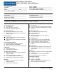
Pre- Delivery Check List 1000, 1500, 2000, 2500, 3000 Series CUSTOMER NAME_____________________________ ADDRESS____________________________________ CITY_________________________________________ STATE________________________ZIP____________ HOME PHONE NUMBER________________________ MODEL NUMBER______________________________ SERIAL NUMBER______________________________ ATTACHMENT MODEL NUMBER_________________ ATTACHMENT SERIAL NUMBER_________________ ENGINE INFORMATION: ENGINE MAKE____________________________
Final Inspection: Check fuel system for leaks. Tank, lines, fittings etc. Check for missing or loose fasteners & decals. Clean / polish. Check overall appearance. Place manuals in a appropriate location (Under Seat) at conclusion.
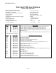
1999 Specifications Cub Cadet 1999 Specifications SERIES 3000 TRACTORS Features and General Specifications: • Hydrostatic Drive w/Cruise Control • Shaft Drive Transmission • Shaft Drive Deck and Front Attachments • Power Steering • Hydraulic Lift • Welded Full Length Twin Channel, 9 gauge Steel Frame • Deck Height Indicator • Halogen Headlights • Taillights w/Reverse Lights • 27" Turning Radius Model 3165 3185* 3186 3205 Factory No.
1999 Specifications Cub Cadet 1999 Specifications (continued) Model 162 Factory No.
NOTES
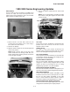
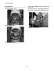
Cub Cadet 3000 1999 3000 Series Engineering Updates 4. Secure the muffler shield with three sheet metal screws. HEAT SHIELD A heat shield has been installed on all 3000 series tractors for 1999. The heat shield prevents the exhaust gases from browning the grass. Use kit #7593927. See Service Advisory CC-371. NOTE: Use a long flat blade screwdriver through the air holes in the grill to tighten the sheet metal screws securely.
Cub Cadet 3000 STEERING WHEEL The thickness of the steering wheel has been increased for operator comfort. ROCK SHAFT ASSEMBLY FOR 3 POINT HITCH 190-365-100 The cylinder arms have been redesigned with two V sections cut out to allow for clearance of the clevis nut on the cylinder shaft. See Service Advisory CC-364.
Cub Cadet 3000 2-3
Cub Cadet 3000 2-4
Cub Cadet 3000 2-5
Cub Cadet 3000 2-6
Cub Cadet 3000 2-7
NOTES
Cub Cadet 3000 Fender Assembly Removal and Reinstallation 1. Slide the seat back and remove the front two pan torx head screws using a T30 torx. 6. Remove the hex bolt securing the differential lock out pedal on the left side of the unit using a 9/16 socket. Remove the “E” clip and the nylon flange bearing from the pivot shaft. 2. Slide the seat forward and remove the rear two pan torx head screws using a T30 torx. 3. Pivot the seat assembly to the side and disconnect the seat safety switch.
Cub Cadet 3000 12. Remove all four running board hex bolts from the tractor using a 1/2” socket. See figure 5. 15. Raise the rear fender high enough to access the hydraulic lift handle clamp. See figure 7. NOTE: There are two bolts fastening the running boards to the frame where the foot pads connect and there are two bolts fastening the running boards to the dash panel. 16. Loosen the clamp connecting the hydraulic lift handle to the center lift valve using a 1/2” socket.
Cub Cadet 3000 4-1
Cub Cadet 3000 4-2
Cub Cadet 3000 4-3
Cub Cadet 3000 4-4
Cub Cadet 3000 4-5
Cub Cadet 3000 4-6
Cub Cadet 3000 4-7
Cub Cadet 3000 4-8
Cub Cadet 3000 4-9
Cub Cadet 3000 4 - 10
Cub Cadet 3000 4 - 11
Cub Cadet 3000 4 - 12
Cub Cadet 3000 4 - 13
Cub Cadet 3000 4 - 14
Cub Cadet 3000 Removal and Replacement of the Power Steering Cylinder CAUTION: Slowly remove the hydraulic lines from the cylinder. Test for pressure in the lines before removal. 5. Remove both of the hex head screws and the hex flange nuts from the cylinder mounting bracket using a 9/16 socket and a 9/16 wrench. See figure 3. 1. Place an oil pan directly under the steering cylinder. This will catch the hydraulic fluid that will be drained from the lines and the cylinder. 2.
Cub Cadet 3000 Cylinder Rod Ball Joint Hex Jam Nut Approx. 2.75" Hex Jam Nut “O” Rings CAUTION ON THE NEXT STEP: There are “O” rings between the cylinder block and the fittings. Extreme care should be used to hold the fittings in place while loosening the hex jam nuts, or damage will occur to the “O” rings. Replacement of the “O rings” is recommended. Hex Jam Nut Ball Joint 14. Hold the hydraulic cylinder elbow fittings in place with a 5/8 wrench, and loosen the hex jam nuts with an 11/16 wrench.
Cub Cadet 3000 Cub Cadet 3000 Series Char-Lynn 2 Series Steering Control It is recommended that the steering control be thoroughly cleaned before any repairs are attempted. When cleaning, be sure all open ports are sealed. The following information may be used in the inspection and repair of Eaton’s Char-Lynn 2 series steering control units. When ordering replacement parts, give the product number and date code.
Cub Cadet 3000 Remove the end cap from the gerotor assembly. Remove the gerotor assemblies outer ring. NOTE: The gerotor assembly may/may not remain intact during removal. Figure 4. Figure 6. Remove the o-ring seal from the gerotor assemblies outer ring. Remove both the seal ring and o-ring seal from the gerotors inner star. Figure 5. Figure 7.
Cub Cadet 3000 Remove the gerotors inner star from the drive. Remove the o-ring seal from the wear plate. Figure 8. Figure 11. Remove the spacer. Remove the wear plate from the housing assembly. Figure 9. Figure 12. Remove the drive from the spool/sleeve assembly. Remove the o-ring from the control housing. Figure 10. Figure 13.
Cub Cadet 3000 The spool/sleeve assembly may be removed from the control valve housing in either the vertical or horizontal position. Using a small screwdriver or similar type tool, remove the cross pin from the spool/sleeve assembly. VERTICAL POSITION Carefully reposition the control valve assembly in the vertical position with the meter end of the control valve housing pointing upward. Remove the spool/sleeve assembly from the control valve housing.
Cub Cadet 3000 Carefully remove the spring retaining ring from the centering springs. Turn the valve housing over and remove the two bearing races and thrust bearing. Figure 17. Figure 19. Carefully remove the centering springs from the spool. Using the small screwdriver or similar tool, remove the dust seal. Caution must be used not to scratch or damage the dust seals counter bore when removing the dust seal. NOTE: It is not necessary nor recommended to remove the external ring from the spool.
Cub Cadet 3000 Again using a small screwdriver or similar tool, remove the quad ring seal from the valve housing. Shown here are both the relief valve check and check ball assemblies. The relief valve check assembly is optional. Figure 21. Figure 23. Using a 7/8 in. socket or end wrench, remove the relief valve check or check ball plug. REASSEMBLY Prior to the reassembly of the steering control, replace all worn and damaged parts and/or assemblies along with all seals and sealing rings.
Cub Cadet 3000 Install the sleeve into the valve housing. After the seal is installed, turn the valve housing over and remove the sleeve, races and bearing. Figure 25. Figure 27. Using caution to retain the races, bearing and sleeve in the valve housing, carefully turn the assembly over and set it on a clean flat surface. Together, the housing, races, bearing and sleeve create a groove into which the quad seal can be installed.
Cub Cadet 3000 Shown here is the correct orientation of the spool/sleeve centering springs. Two sets of (3) each curved springs in the center and (1) each flat piece on the outside. Next install one set of the 3 curved centering springs between the two flat pieces. Figure 31. Figure 29. Then install the final set of 3 curved centering springs between the flat piece and the previously installed curved centering springs. To install the centering springs on the spool, first install the two flat pieces.
Cub Cadet 3000 Center the centering springs and install the spring retaining ring over the springs. Push the spool assembly into the sleeve until the centering springs are firmly positioned into the notches located in the sleeve. Figure 33. Figure 35. Lubricate the spool assembly and install into the sleeve, aligning the centering springs with the notches machined in the sleeve. Insert the cross pin into the spool/sleeve assembly. Figure 36. Figure 34.
Cub Cadet 3000 Supporting the valve housing in the upright position, lubricate and install the bearing races and thrust bearing. Lubricate and install the o-ring seal into the groove located in the control valve housing. NOTE: The thrust bearing must be installed between the two bearing races. Figure 39. Figure 37. Lubricate and install the spool/sleeve assembly into the valve housing. Figure 38.
Cub Cadet 3000 Lubricate and install the o-ring seal into the groove located in the wear plate. Lubricate and install both the gerotor star and outer ring. Install by aligning the splines of the star with the drive. After installation, rotate the gerotors outer ring to align with the housing cap screw holes. NOTE: The grooved side of both gerotor star and outer ring must face upward. Figure 41.
Cub Cadet 3000 Lubricate and install both the o-ring seal and seal ring into the gerotor star. Install the o-ring in the groove located in the star first and then the seal ring. Prior to the installation of the end cap, freely lubricate the gerotor star seal ring. Figure 45. Figure 47. Lubricate and install the o-ring seal into the groove located in the gerotors outer ring. Figure 46. Install the end cap onto the gerotor assembly by aligning the cap screw holes. Figure 48.
Cub Cadet 3000 Install the end cap retaining cap screw and tighten in a crisscross sequence. Torque to 140-160 in. lbs. The steering control is now ready for test and installation. Figure 52. Figure 49. Install the check ball or optional relief valve check as shown here. Figure 50. Torque plug to 15 in. lbs. Figure 51.
Cub Cadet 3000 6 - 14
Cub Cadet 3000 6 - 15
Cub Cadet 3000 6 - 16
Cub Cadet 3000 6 - 17
NOTES
Cub Cadet 3000 Removal and Replacement for the Center Lift Cylinder CAUTION: Slowly remove the hydraulic lines from the cylinder. Test for pressure in the lines before removal. 6. Remove both hydraulic connectors from the lift cylinder using a 7/8” open end wrench. NOTE: The front connector on the lift cylinder hydraulic line runs to the top port of the lift valve. The back connector on the lift cylinder hydraulic line runs to the bottom port of the lift valve.
NOTES
Cub Cadet 3000 Removal and Replacement of the Pump Adapter Prior to removing the pump adapter, it is necessary to remove the fender assembly. Bottom Coupling Half 1. Remove the side panels and disconnect the spark plug wires. Sleeve Bearing Lower Steering Shaft 2. Remove all four of the hex head tapp screws that connect the drive shaft to the pump adapter using a 3/8 socket. See figure 1. Drive Shaft Tap Screws FIGURE 3. 6. Slide the drive shaft towards the left frame rail.
Cub Cadet 3000 9. Finger loosen the pump adapter nut until it is flush with the end of the hydro input shaft. INSTALLATION OF THE NEW PUMP ADAPTER 1. Clean the hydrostatic input shaft of any debris. See figure 7. 10. Place a 13/16 socket against the nut with the opened end of the socket facing away from the nut. See figure 6. 2. Apply a light coat of loctite 803 to the taper of the input shaft. See figure 7. 11. Place the new pump adapter, cupped side in, over the opened end of the 13/16 socket.
Cub Cadet 3000 6. Line up the drive shaft with the new pump adapter. 9. Tighten the hex bolts and shoulder nuts securing the pump adapter assembly, using a 7/16 wrench and a 7/16 socket. See figure 10. NOTE: If there is more than an 1/8” gap between the drive shaft and pump adapter place the spacer in between the the drive shaft and the pump adapter. Do not force the spacer in if it does not fit. 7. Install the new bolts through the drive shaft, pump adapter, and the fan. 8.
NOTES
Cub Cadet 3000 BDU-21L-500 Auxiliary Pressure Test Prior to performing this test, it is necessary to remove the deck and fender assemblies. 6. Install the pressure test kit into the unit with the pressure gauge standing straight up. See figure 3 and 4. 1. Remove the hex cap screw securing the double valve clamp to the charge pump using an 11mm swivel socket. See figure 1. 7. Reinstall the double valve clamp to the charge pump. See figure 1. 2.
Cub Cadet 3000 If the pressure readings are not meeting the specifications, the charge pump is faulty. 13. Increase the throttle to full. Record the hydro reading at the pressure gauge. The reading should be between 200 PSI and 650 PSI. See figure 5. If the pressure readings are meeting specifications, the charge pump is not faulty and the mechanical system must be checked. NOTE: This system should not read higher than 650 PSI. The relief valve is set to 650 PSI in the auxiliary manifold. FIGURE 5. 14.
Cub Cadet 3000 Hydrostatic Transmission Pressure Test Setup 4. With tractor running, apply parking brake. Bill of Materials • 2 - 3000 P.S.I. Hydraulic Gauges • 1 - 200 P.S.I Hydraulic Gauge • 2 - 9/16-18 Straight Thread O-ring & JIC fitting (JIC dependent on hose fittings) • 3 - 3000 P.S.I. hoses of adequate lengths (Connect as shown in FIG 1) • 1 - T fitting • 1 - needle valve 5. Continue holding the brake. depress the forward foot pedal until max. pressure is seen on right side gauge. 6.
NOTES
Cub Cadet 3000 Removal and Replacement of the Hydraulic Steering Pump Prior to removing the steering pump, it is necessary to remove the fender assembly. CAUTION: Slowly remove the hydraulic lines from the hydraulic steering pump. Test for pressure in the lines before removal. 1. Place an oil pan directly under the hydraulic steering pump. This will catch the hydraulic fluid that will be drained from the lines and the pump. 2.
Cub Cadet 3000 10. Remove the hydraulic tubes from the hydraulic steering pump. 14. Remove the hydraulic steering pump from the tractor. NOTE: If the hydraulic tubes do not want to come out, use a small mallet and tap them out of the ports. Be careful not to damage the tubes. Return Auxiliary Steering 11. Inspect the “O” rings on the connectors for damage. If damaged, replace. NOTE: Place a small amount of grease on the “O” rings and cover the connector surface completely for reinstallation.
Cub Cadet 3000 Removal and Replacement of the Hydraulic Valve Prior to removing the hydraulic valve, it is necessary to remove the fender assembly. 7. Remove the side valve clamp that holds the inlet tube to the valve body using a 7/16 socket. See figure 3. CAUTION: Slowly remove the hydraulic lines from the hydraulic valve. Test for pressure in the lines before removal. NOTE: All the hydraulic lines and tubes going into the hydraulic valve ports have two “O” rings on each connector. See figure 4. 1.
Cub Cadet 3000 11. Inspect the “O” rings for damage. If damaged, replace. See figure 4. 12. Remove all the remaining hardware from the valve body using a 7/16 socket. “O” Rings FIGURE 4. 13. Remove the valve mounting brackets. See figure 5. NOTE: Write down the correct positions of the mounting brackets. The brackets can be installed backwards if not properly marked. 14. Remove the squared lift link.
Cub Cadet 3000 Engine Removal and Replacement IMPORTANT: Use proper safety procedures when working on the tractor. 8. Partially close the hood to allow access to the grill fasteners. See figure 3. 1. Open the hood and remove the battery box cover. 9. Squeeze all four grill fasteners and release the grill. See figure 3. 2. Remove the negative and positive battery terminal connectors from the battery using a 5/16 socket. 3.
Cub Cadet 3000 Ground to Heat Shield 14. Remove both the choke and the throttle cables. See figure 5. Spark Plug Boot and Wire NOTE: use a marker and mark the holes and cable alignment before removal. Solenoid Throttle Connector Positive “Hot” Lead Wire Choke Starter E-Vac FIGURE 7. 17. Remove the fuel line from the engine. NOTE: Make sure the fuel line is fully drained and secured in a safe place during engine removal. FIGURE 5. 15. Disconnect the vacuum tube from the E-Vac check valve.
Cub Cadet 3000 21. Remove all four of the hex bolts securing the drive shaft to the engine flywheel using a 7/16 socket and extension. See figure 9. Hex Bolts Hex Bolts FIGURE 11. Drive Shaft 28. Slowly raise the engine and mounting plate from the unit while a helper guides the drive shaft out of the flywheel screen. See figure 12. FIGURE 9. 22. Remove the PTO idler arm extension spring. See figure 10. Engine Brackets 23.
NOTES
Cub Cadet 3000 Transmission Removal and Installation Prior to removing the transmission, it is necessary to remove the fender assembly. Tap Screws 1. Loosen the fuel line clamp at the gas tank and slide it down the fuel line. 2. Remove the fuel line from the gas tank. 3. Remove the fuel sensor connector. 4. Remove all four of the hex bolts and lock nuts from the rear hitch plate panel using a 9/16 socket and a 9/16 wrench. Remove the hitch plate. Pump Adapter 5. Remove the gas tank from the tractor. 6.
Cub Cadet 3000 17. Brace the transmission. 18. Remove all four of the front transmission support bracket to frame hex cap screws and hex flange lock nuts using a 9/16 wrench and a 9/16 socket. See figure 5. 20. Remove both transmission to frame “U” bolts using a 3/4" socket. See figure 7. NOTE: The “U” bolts have a lower point on one side. The point goes towards the rear of the unit during reassembly. See figure 7.
Cub Cadet 3000 Transmission Inspection and Disassembly 1. Inspect the pump adapter to be certain that it is turning the hydraulic input shaft. See figure 1. 4. Inspect the clearance between the hydro bypass spring plate and the bypass valve on the hydro pump. See figure 3. 2. Inspect the center hex jam nut and flat washer on the pump adapter to be certain that it is not loose. See figure 1. NOTE: There should be free play in between the plate and the bypass valve.
Cub Cadet 3000 6. Remove both clamps from the hydro pickup tube using a 7/16 wrench on the upper hex screw and a 3/8 wrench on the lower hex screw. 7. Remove the hydro pickup tube and inspect the tube for any contamination that would restrict the hydro oil flow. See figure 5. 13. Remove the hydrostatic transmission from the differential transmission and inspect the case drain holes on the hydro and the differential. See figure 7. Drain Hole 8. Inspect the “O” ring at each end of the hydro pickup tube.
Cub Cadet 3000 18. Remove the center hub lock nuts on the hub assemblies using a 1 and 5/16” socket. See figure 9. Hex Washer Tap Screw Transmission Plate Gasket NOTE: The torque on the center hub nut is 180250 ft-lbs. 1” Long Hex Screws 19. Remove the brake mounting bracket from the differential assembly by rotating the brake disk until the access holes are directly above the hex washer screws.
Cub Cadet 3000 Bevel Gear 34. Remove the input pinion gear assembly from the case. See figure 15. Output Shaft Spur Gear Inner Bearing Block Outer Bearing Block Differential Lock Actuator Shaft Input Pinon Gear FIGURE 12. 32. Write down the shim orientations for both sides of the output shaft. See figure 13. 35. Remove the four hex cap screws from the differential housing using a 9/16 socket. See figure 16. Pin Engaged Differential Lock Collar Ass’y. Differential Lock Housing FIGURE 15.
Cub Cadet 3000 3000 Series Neutral Control Adjustment The following information will correct forward or rearward movement (creeping). Hydrostatic Transmission 1. Drive the tractor for a few minutes to warm up the hydrostatic transmission. Extension Access Hole 2. Raise the rear of the tractor off the ground. 3. Remove all four of the wheel hub nuts securing the right rear wheel assembly to the wheel hub, using a 3/4" socket and extension. Hex Cap Screw 4. Remove the right wheel assembly.
NOTES
Electrical Briggs & Stratton and Kawasaki Kohler 17 - 1
629-3057 Wiring Harness 3000 Series — B&S Engine Electrical 17 - 2
629-3057 Wiring Harness 3000 Series — B&S Engine Electrical 17 - 3
629-3056 Wiring Harness 3000 Series — Kohler Engine Electrical 17 - 4
629-3045 Wiring Harness 3000 Series — Kawasaki Engine Electrical 17 - 5
629-3057 Wiring Harness 3000 Series — B&S Engine IGNITION OFF Electrical 17 - 6
629-3057 Wiring Harness 3000 Series — B&S Engine STARTING 1 Electrical 17 - 7
629-3057 Wiring Harness 3000 Series — B&S Engine STARTING 2 Electrical 17 - 8
629-3057 Wiring Harness 3000 Series — B&S Engine RUN / CHARGE Electrical 17 - 9
629-3056 Wiring Harness 3000 Series — Kohler Engine RUN / CHARGE Electrical 17 - 10
629-3057 Wiring Harness 3000 Series — B&S Engine LIGHTING Electrical 17 - 11
629-3057 Wiring Harness 3000 Series — B&S Engine PTO ON 1 Electrical 17 - 12
629-3057 Wiring Harness 3000 Series — B&S Engine PTO ON 2 Electrical 17 - 13
629-3057 Wiring Harness 3000 Series — B&S Engine SAFETY / REVERSE Electrical 17 - 14
629-3057 Wiring Harness 3000 Series — B&S Engine SAFETY / PTO-SEAT Electrical 17 - 15
629-3057 Wiring Harness 3000 Series — B&S Engine SAFETY / PTO-BRAKE Electrical 17 - 16
629-3057 Wiring Harness 3000 Series — B&S Engine SAFETY / OK Electrical 17 - 17
629-3057 Wiring Harness 3000 Series — B&S Engine SAFETY / OK Electrical 17 - 18
629-3057 Wiring Harness 3000 Series — B&S Engine Electrical 17 - 19
629-3057 Wiring Harness 3000 Series — B&S Engine Electrical 17 - 20
629-3057 Wiring Harness 3000 Series — B&S Engine Electrical 17 - 21
629-3057 Wiring Harness 3000 Series — B&S Engine Electrical 17 - 22
629-3057 Wiring Harness 3000 Series — B&S Engine Electrical 17 - 23
629-3057 Wiring Harness 3000 Series — B&S Engine Electrical 17 - 24
629-3057 Wiring Harness 3000 Series — B&S Engine Electrical 17 - 25
629-3057 Wiring Harness 3000 Series — B&S Engine Electrical 17 - 26
629-3057 Wiring Harness 3000 Series — B&S Engine Electrical 17 - 27
629-3057 Wiring Harness 3000 Series — B&S Engine Electrical 17 - 28
629-3057 Wiring Harness 3000 Series — B&S Engine Electrical 17 - 29
629-3057 Wiring Harness 3000 Series — B&S Engine Electrical 17 - 30
629-3057 Wiring Harness 3000 Series — B&S Engine Electrical 17 - 31
629-3057 Wiring Harness 3000 Series — B&S Engine Electrical 17 - 32
629-3057 Wiring Harness 3000 Series — B&S Engine Electrical 17 - 33
629-3057 Wiring Harness 3000 Series — B&S Engine Electrical 17 - 34
629-3057 Wiring Harness 3000 Series — B&S Engine Electrical 17 - 35
629-3057 Wiring Harness 3000 Series — B&S Engine Electrical 17 - 36
629-3057 Wiring Harness 3000 Series — B&S Engine Electrical 17 - 37
629-3057 Wiring Harness 3000 Series — B&S Engine Electrical 17 - 38
629-3057 Wiring Harness 3000 Series — B&S Engine Electrical 17 - 39
629-3057 Wiring Harness 3000 Series — B&S Engine Electrical 17 - 40
629-3057 Wiring Harness 3000 Series — B&S Engine Electrical 17 - 41
NOTES
Cub Cadet 3000 The BDU-21L transmission offers an optional Implement (auxiliary) pump. The auxiliary circuit provides a rated flow of 1.5 gpm and 500 PSI operating pressure at a 3200 RPM pump speed. Fluid from the charge pump flows first to the implement control valve, then to the charge relief valve and charge check valves in the center section. This requires an “open center” type control valve to allow fluid flow to return to the transmission.
Cub Cadet 3000 18 - 2
Cub Cadet 3000 FLUIDS Fluids used in Cub Cadet 3000 Series tractors have been carefully selected. Only use Cub Cadet oil part no. 737-3055A for quarts or 737-3054A for gallons. SAFETY PRECAUTIONS Certain procedures may require the vehicle to be disabled (wheels raised off the ground, engine disconnected, etc.) in order to prevent possible injury to the technician and bystanders. Some cleaning solvents are flammable.
Cub Cadet 3000 18 - 4
Cub Cadet 3000 18 - 5
Cub Cadet 3000 MINOR REPAIR GENERAL INFORMATION Minor repairs may be performed, following the procedures in this section, without voiding the unit warranty. Carefully pull the seal out of the housing bore. A "hook" type tool may be used to grasp the seal and pull it out, or a slide hammer type puller may be used to remove the seal. Care must be taken so as not to damage the housing bore, shaft sealing surface, or bearing. Once removed, the seal is not reusable.
Cub Cadet 3000 BYPASS VALVE Remove the bypass valve plug with a 9/16" hex wrench. Remove the bypass valve plug, spool and spring from the transmission center section. Inspect the valve spool and mating bore in the center section for damage or foreign material. The spool must move freely. It is recommended that the o-rings be replaced. Retain the valve spring to the valve spool with petroleum jelly. Install the valve spool, spring and plug (with o-ring) into the center section. Torque the plug to 7-10 ft.
Cub Cadet 3000 Remove the swashplate assembly and cradle bearings from the housing. NOTE: The cradle bearings in newer BDU-21L transmissions are not removable from the housing. If damage is present, a new housing kit is necessary. Inspect the cradle bearing’s low friction coating for wear. Inspect the swashplate and thrust bearing for any unusual wear or damage. If damage to the swashplate or cradle bearings is found then inspect the housing for possible damage. Replace complete assemblies as necessary.
Cub Cadet 3000 Install the thrust washer and pump cylinder block spring onto the pump shaft. Install the two aligning pins, and install a new gasket onto the housing. Install the springs piston washers and pistons into the cylinder block. The pistons must move freely in their bores. Lubricate the running surfaces of the cylinder blocks and the center section.
NOTES
NOTES
NOTES