Safety • Assembly • Operation • Tips & Techniques • Maintenance • Troubleshooting • Parts Lists • Warranty OPERATOR’S MANUAL 31AE9PSV710 31AE9LSU710 31AE9LSU756 Model 31AE9PSV710 shown Two Stage Snow Thrower — Models 930 SWE & 933 SWE IMPORTANT READ SAFETY RULES AND INSTRUCTIONS CAREFULLY BEFORE OPERATION Warning: This unit is equipped with an internal combustion engine and should not be used on or near any uniiproved forest-covered, brushcovered or grass-covered land unless the engine’s exhaust system
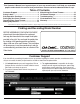
This Operator’s Manual is an important part of your new snow thrower. It will help you assemble, prepare and maintain the unit for best performance. Please read and understand what it says. Table of Contents Customer Support............................................... 2 Safety Labels....................................................... 3 Safe Operation Practices.................................... 4 Setting Up Your Snow Thrower........................... 6 Operating Your Snow Thrower..................
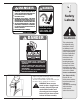
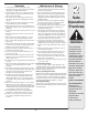
$!.'%2 +%%0 !7!9 &2/- 2/4!4).' )-0%,,%2 !.$ !5'%2 #/.4!#4 7)4( )-0%,,%2 /2 !5'%2 #!. !-054!4% (!.$3 !.$ &%%4 53% #,%!. /54 4//, 4/ 5.#,/' $)3#(!2'% #(54% $)3%.'!'% #,54#( ,%6%23 34/0 %.').% !.$ 2%-!). "%().$ (!.$,%3 5.4), !,, -/6).' 0!243 (!6% 34/00%$ "%&/2% 5.#,/'').' /2 3%26)#).' -!#().% 4/ !6/)$ 4(2/7. /"*%#43 ).*52)%3 .%6%2 $)2%#4 $)3#(!2'% !4 "934!.$%23 53% %842! #!54)/. 7(%. /0%2!4).' /. '2!6%, 352&!#%3 2%!$ /0%2!4/2g3 -!.5!, #,%!. /54 4//, $!.'%2 1 Safety Labels !6/)$ ).
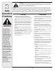
2 Safe Operation Practices WARNING This symbol points out important safety instructions which, if not followed, could endanger the personal safety and/or property of yourself and others. Read and follow all instructions in this manual before attempting to operate this machine. Failure to comply with these instructions may result in personal injury. When you see this symbol.
Operation Maintenance & Storage 1. Do not put hands or feet near rotating parts, in the auger/impeller housing or chute assembly. Contact with the rotating parts can amputate hands and feet. 2. The auger/impeller control lever is a safety device. Never bypass its operation. Doing so makes the machine unsafe and may cause personal injury. 3. The control levers must operate easily in both directions and automatically return to the disengaged position when released. 4.
3 IMPORTANT: Two replacement auger shear pins are included with this manual (or stowed in the plastic handle panel). Refer to the Maintenance section for more information regarding shear pin replacement. NOTE: All references in this manual to the left or right side of the snow thrower is from the operating position only. Exceptions, if any, will be specified. Setting Up Your Snow Thrower IMPORTANT: This unit is shipped with the engine full of oil.
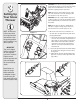
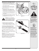
3 3. a. Remove the flat washer and hairpin clip from the end of the chute directional control. See Figure 3-3. b. Insert the end of the chute directional control into the chute bracket and secure with the flat washer and hairpin clip just removed. If necessary, the chute bracket can be adjusted. Refer to the Adjustments section. Setting Up Your Snow Thrower IMPORTANT: Prior to operating your snow thrower, refer to Auger Control Test in the Operation section.
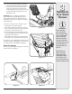
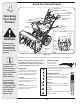
3 Shift Lever Chute Tilt Control Auger Control Drive Control Setting Up Your Snow Thrower Specifications are subject to change without notification or obligation. Images may not reflect your exact model and are for reference purposes only.
3 Adjusting Drive and Auger Controls 1. From beneath the handle, pull downward on the appropriate cable and unhook the spring found on the end of the cable from its respective actuator bracket. Refer to Figures 3-8 and 3-9. Setting Up Your Snow Thrower 2. Slide the spring up the cable to expose the cable coupler threads and lock nut. Refer to Figure 3-10. Adjust the lock nut as follows: 3.
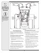
4 Operating Your Snow Thrower Know Your Snow Thrower Drive Control Shift Lever Two-Way Chute Control™ Auger Control Gas Cap Fuel Tank Oil Fill Wheel Steering Control Headlight Chute Directional Control Chute Assembly Engine Controls Recoil Starter Handle Electric Starter Outlet Primer WARNING Read, understand, and follow all instructions and warnings on the machine and in this manual before operating.
Auger Control The two-way chute control is located on the left side of the dash panel and is used to control the distance of snow discharge from the chute. • To change the angle/distance which snow is thrown, pivot the joystick forward or backward. $2)6% #/.42/, Chute Directional Control The chute directional control is located on the left side of the snow thrower. • To change the direction in which snow is thrown, crank clockwise to discharge to the left and counterclockwise to discharge to the right.
4 Operating Your Snow Thrower Gas & Oil Fill-Up Service the engine with gasoline and oil as instructed in the Tecumseh Engines manual packed separately with your snow thrower. Read instructions carefully. WARNING: Use extreme care when handling gasoline. Gasoline is extremely flammable and the vapors are explosive. Never fuel machine indoors or while the engine is hot or running. Extinguish cigarettes, cigars, pipes and other sources of ignition. Starting The Engine 1.
Stopping The Engine Operating Tips Run engine for a few minutes before stopping to help dry off any moisture on the engine. 1. Move throttle control to STOP position. NOTE: Allow the engine to warm up for a few minutes. The engine will not develop full power until it reaches operating temperature. 2. Remove the ignition key (Do not turn key) to prevent unauthorized use of equipment. WARNING: The temperature of the muffler and the surrounding areas may exceed 150° F. Avoid these areas. 3.
5 Shift Cable If the full range of speeds (forward and reverse) cannot be achieved, refer to the figure to the left and adjust the shift cable as follows: 1. Place the shift lever in the fastest forward speed position. Making Adjustments 2. Loosen the hex nut on the speed selector pivot bracket. See Figure 5-1. 3. Pivot the bracket downward to take up slack in the cable. 4. Retighten the hex nut. 5. If further adjustment is needed, you may also utilize the upper or lower hole in the pivot bracket.
5 Skid Shoes The space between this shave plate and the ground can be adjusted. For close snow removal, place skid shoes in the low position. Use middle or high position when area to be cleared is uneven. 1. Adjust skid shoes by loosening the six hex nuts, washers, and carriage bolts and moving skid shoes to desired position. See Figure 5-5. 2. Make certain the entire bottom surface of skid shoes are against the ground to avoid uneven wear on the skid shoes.
6 Wheels At least once a season, remove both wheels. Clean and coat the axles with a multipurpose automotive grease before reinstalling wheels. Chute Directional Control Once a season, the spiral end on the chute directional control should be greased with multipurpose automotive grease. Maintaining Your Snow Thrower Auger Shaft At least once a season, remove the shear pins on auger shaft. Spray lubricant inside shaft, around the spacers.
6 Shave Plate and Skid Shoes The shave plate and skid shoes on the bottom of the snow thrower are subject to wear. Check these periodically and replace as necessary. Skid Shoes NOTE: The skid shoes on this machine have two wear edges. When one side wears out, they can be rotated 180° to use the other edge. Skid Shoe Shave Plate Maintaining Your Snow Thrower 1. Remove the six carriage bolts, hex nuts, and bell washers that secure the two skid shoes to the sides of the auger housing. Refer to Figure 6-3.
6 Maintaining Your Snow Thrower Remove 6. Slip the auger control belt (the front belt) off the engine pulley. 7. Pull the brake bracket assembly towards the cable guide roller and unhook the auger cable “Z” fitting. See Figure 6-9. 8. Remove the upper bolts which attach the auger housing assembly to the frame assembly using a 9/16” wrench. Refer to Figure 6-4 on previous page. 9.
6 If also replacing the drive belt, proceed to the “Drive Belt” instruction. If not, reassemble by performing the previous steps in the opposite order and manner of removal. Proper Adjustment: With the auger clutch lever in the disengaged position, the top surface of the new belt should be even with the outside diameter of the pulley. Maintaining Your Snow Thrower 1.
6 Changing Friction Wheel The rubber on the friction wheel is subject to wear and should be checked after the first 25 hours of operation, and periodically thereafter. Replace the friction wheel if any signs of wear or cracking are found. • Drain the gasoline from the snow thrower, or place a piece of plastic under the gas cap. Maintaining Your Snow Thrower • Tip the snow thrower up and forward, so that it rests on the housing. • Remove screws from the frame cover underneath the snow thrower.
• Reassemble the new friction wheel to the hub assembly, tightening the four screws in rotation and with equal force. It is important to assemble the friction wheel symmetrically for proper functioning. Hub Assembly • Insert the pin from the shift arm assembly into the friction wheel assembly and hold assembly in position. Refer to Figure 6-16. 6 Maintaining Your Snow Thrower • Slide the hex shaft through the left side of the housing and through the friction wheel assembly.
7 Off-Season Storage If the snow thrower will not be used for 30 days or longer, or if it is the end of the snow season when the last possibility of snow is gone, the equipment needs to be stored properly. Follow storage instructions below to ensure top performance from the snow thrower for many more years. Preparing Engine Preparing Snow Thrower NOTE: Refer to the engine manual for more detailed information on preparing the snow thrower engine for storage.
Problem Engine fails to start Cause Remedy 1. Choke not in ON position. 1. Move choke to ON position. 2. Spark plug wire disconnected. 2. Connect wire to spark plug. 3. Fuel tank empty or stale fuel. 3. Fill tank with clean, fresh gasoline. 4. Engine not primed. 4. Prime engine as instructed in “Operating Your Snow Thrower”. 5. Faulty spark plug. 5. Clean, adjust gap, or replace. 6. Blocked fuel line. 6. Clean fuel line. 7. Safety key not in ignition on engine. 7.
Models 930 SWE & 933 SWE 24 50 20 53 58 12 41 43 19 30 55 37 4 35 43 37 52 21 48 34 18 57 33 38 25 36 21 21 54 1 47 11 15 63 17 6 22 11 11 22 60 65 64 5 56 14 10 62 13 61 21 16 26 45 8 3 8 42 32 3 51 78 66 40 74 70 23 28 79 75 49 26 7 31 27 79 49 49 69 72 71 49 73 75 77 7 74 32 59 2 70 40 44 67 68 76 24 39 46 9
Part No. Description Ref. No. Part No. 05244B Housing, Bearing 41 736-3008 Washer, .344 x .75 x .12 2 784-0315A Housing, Double D Bearing 42 736-3046A Washer, 1.01 x 1.86 x .06 3 618-0436 Gear Box Assembly, Auger 43 738-0281 Screw, Shoulder, .625 x .17 4 618-0281A Bracket Assy, Auger Brake 44 738-04155 Pin, Shear, .25 x 1.
Models 930 SWE & 933 SWE 1 11 12 13 3 21 6 5 8 55 9 4 16 6 17 54 30 14 10 7 8 18 44 20 19 62 14 26 11 43 16 63 37 39 25 23 48 24 56 53 46 36 27 35 33 45 30 29 49 48 28 47 58 60 34 61 59 52 23 42 2 15 57 22 51 51 26 32 31 38 41 50 40
Part No. Description Ref. No. Part No. 684-04106B Handle Engage Assy - RH 33 731-0846C Upper Chute 2 731-0851A Chute, Flange Keeper 34 714-0104 Pin, Internal Cotter Pin 3 731-04894B Lock Plate 35 710-04187 Hi-Lo Screw, 1/4-15 x 0.5 4 711-04287 Pivot Rod 36 684-04230 2-Way Chute Control™ Assy 5 735-0199A Rubber Bumper 37 731-04954 Steering Control 6 710-04354 Screw, 1/4-20 x.375 38 710-04326 Screw, #8-16 x 0.
Models 930 SWE & 933 SWE 81 94 96 78 89 88 85 79 91 90 80 26 95 84 93 98 49 44 83 86 87 92 78 26 79 77 82 62 99 11 22 97 9 38 63 17 24 3 65 4 40 33 25 20 53 34 68 75 66 43 B 5 67 35 8 27 32 51 38 70 56 60 59 76 31 A 19 17 A 36 20 61 64 63 2 34 8 6 18 16 23 71 37 25 43 74 44 46 62 42 54 12 15 B 7 29 21 28 14 1 41 31 50 26 61 49 13 73 55 39 52 58 38 72 47 10 45 31 30 57 69 17 48 28
Part No. Description Ref. No. Part No. 05244B Housing, Bearing 42 732-0121 Spring, Extension 2 618-0279 Dogg, Steering Drive, LH 43 732-0209 Spring, Extension 3 618-0280 Dogg, Steering Drive, RH 44 712-04064 Flange, Lock Nut, 1/4-20 4 618-0282E Shaft Assembly, Steering 45 736-0158 Washer, Lock, 5/8 5 618-04178 Assembly, Friction Wheel 46 710-0751 Screw, 1/4-20 x .
9 Parts List Models 930 SWE & 933 SWE Continued from previous page Ref. No. Part No. Description 81 710-1245B Screw, Hx Cap 5/16-24 82 710-0654A Screw, 3/8-16 x 1.00 83 736-0173** Washer, Flat, .28 x .74 x .063 84 714-0118 Key, Square, 1/4 x 1.5 85 790-00167A Bracket, Belt Keeper 86 731-2531 Cover, Belt 87 732-0303 Spring, Extension 88 732-0705 Guide, Chute Cable 89 736-0247 Washer, Flat, .406 x 1.25 90 748-0234 Spacer, Shoulder 91 736-0159** Washer, Flat, .349 x .
MANUFACTURER’S LIMITED COMMERCIAL WARRANTY FOR: The limited warranty set forth below is given by Cub Cadet LLC with respect to new merchandise used for commercial purposes and purchased and used in the United States and/or its territories and possessions, and by MTD Products Limited with respect to new merchandise purchased and used in Canada and/or its territories and possessions (either entity respectively, “Cub Cadet”). c.
MANUFACTURER’S LIMITED WARRANTY FOR The limited warranty set forth below is given by Cub Cadet LLC with respect to new merchandise purchased and used in the United States, its possessions and territories, and by MTD Products Limited with respect to new merchandise purchased and used in Canada and/or its territories and possessions.