
Use and Care Manual

8 Section 3— ASSembly & Set-Up
4. Secure the handle by tightening the plastic knob located
on both the left and right sides of the handle. Remove
and discard any rubber bands, if present. They are for
packaging purposes only.
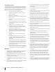
Chute Assembly
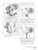
1. Remove hairpin clip, wing nut and hex screw from chute
control head and clevis pin and bow-tie cotter pin from
chute support bracket. See Figure 3-3.
Chute Control Head
Chute
Chute Support
Bracket
Chute Base
Figure 3-3
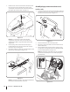
2. Insert chute control rod into chute control head. Push rod
as far into chute control head as possible, keeping the
holes in the rod pointing upward. See Figure 3-4.
Figure 3-4
3. Place chute onto chute base and ensure chute control
rod is positioned under the handle panel. Install hex bolt
previously removed but do not secure with wing nut at this
time. See Figure 3-5.
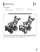
Assembly (If Equipped with 4-Way Chute Control)
Remove all loose parts before assembling.
Handle Assembly
1. Place the shift lever in the Forward-6 position as shown in
Figure 3-1 inset.
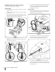
2. Cut zip ties securing chute control rod to the lower handle
and set it aside.
3. Observe the lower rear area of the snow thrower to be sure
both cables are aligned with roller guides before pivoting
the handle upward. Pivot the handle upward.
Figure 3-1
NOTE: Make certain the cables are seated properly in the
roller guides. See Figure 3-2.
Figure 3-2