AS Overview < Remove packaging materials from snow blower. « Rotate Handle into the upright position. Refer to Handle Assembly. « Installment chute, Refer to Chute Assembly Options. « Complete snow blower assembly according to model and equipment, Refer to Set-up, « i necessary make adjustments to ensure proper snow blower operation. Refer to Adjustments. « Add fuel and oil. Refer to the Engine Operator's Manual shipped with snow blower.
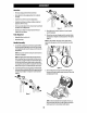
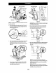
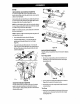
LA 6. Attach the twa carriage bots {b) and nuts {a) removed in Step 2. Finish securing the handle by tightening the top two nuts {c) loosened in Step 2. See Figure or Figure 6 far models with side supports. Figure 6 Refer to Figure 7 below to identify your “Chute Control Style” and continue ta the “Assembly” instructions for your specific style on pages 8-13.
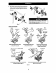
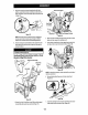
L4101 Side Mounted Chute Rotation Control w/ 3, Remove plastic cap (if present), flat washer {a) and hairpin Manual Pitch clip (b} farm end of chute control rod {Figure 11}, Yo Chute Assembly Chute Controlled Figure 11 4. Inserted of chute control rod into dower bracket and secure with flat washer [2), hairpin ¢lip {b) and plastic cap (f present) removed in Steps 1, If necessary, lower bracket can be adjusted. Refer to Side Chute Control on page 16, ®STOP Continue to Set-Up {page 14).
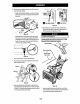
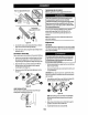
e IR * Chute Control Head 5. Remove hairpin clip {a} from rear of chute control head {Figure 17}, Figure 17 6. Insert chute control rod (b} Ina rear of chute control head | {Figure 17} and secure with hairpin clog {a) removed in Step 5. 2. Secure chute control head to chute support bracket with clevis pin and cotter pin {d) removed in Step T (Figure 14).
LA ° 1 Chute Control Head Chute Control Collar / ~, Chute Support & o Bracket Top View Chute Control (One 0'clock Position) Figure IMPORTANT: Chute will not rotate without squeezing trigger on 2-waylay-way chute control. NOTE:For smoothest operation, cables should all be to the left of the chute control rod. 2. Insert chute conceal rod into chute control head. Push rod as far Into chute control head as possible, keeping hots in rod pointing upward (Figure 20), 5.
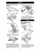
a3 ~ Push chute control rod toward control panel until hole in rod fines up with hole In chute control input collar closest to chute control head and Insert hairpin ip (2} removed in Step. 1 {Figure 25), Figure NOTE; Second hot is used to achieve further engagement of chute contort rod Into pinion agar, if required. Refer to Product Care section for Chute Control Rod adjustments. .
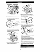
ASSEMBLY 6. Perform one of the fallowing to connect the flex shaft to the chute control rod coupling: « Medals with Overhead Rotational Insert hex end of flex shaft into chute control rod coupling under handier panel {Figure 303, € ton-Hydra Models Figure 33 10, Insert ferrule into top hole of shift lever and secure with carter pin (a) and washer {b) removed in Step 8 {Figure 32). Ferrule may need to be adjusted up ar down.
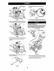
ASSES Chute Control Head Chute Support Bracket Figure 35 NOTE: For smoothest operation, cables should all be to the left of the chaste control rod. 2. Insert round end of chute control rod anti chute control head. Push rod as far anti chute control head as possible, keeping holes in vod pointing upward {Figure 36}, Figure 36 3. Place chute onto chute base and ensure chute control rod is positioned abase lower handle.
Set-Up CHUTE CONTROL CABLE ROUTING (IF EQUIPPED) For models equipped with 2-way or 4-way chute controls, electric chute control and/or chute-pitch controls, ensure contra cables are routed properly.
ASSEMBLY Tull-fess Non Adjustable Drift Cutter Figure 44 2. Rather drift cutters around and position them as shown in Figure 44 10 the outside of the auger housing, 3. Attach drift cutters with carriage bolts (a) and wing nuts (b) removed in Step 1. SKID SHOES (F APPLICABLE) Select medals require the installation to the provided skid shoes, 1. Using the twe carriage buts {a) and hex flange nuts {b) and flat washers (if equipped) (0, secure the skid shoes to the auger abusing {d).