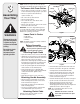
Safety • Assembly • Operation • Tips & Techniques • Maintenance • Troubleshooting • Parts Lists • Warranty OPERATOR’S MANUAL Rear Tine Tiller — Model Series 450 IMPORTANT READ SAFETY RULES AND INSTRUCTIONS CAREFULLY BEFORE OPERATION Warning: This unit is equipped with an internal combustion engine and should not be used on or near any unimproved forest-covered, brushcovered or grass-covered land unless the engine’s exhaust system is equipped with a spark arrester meeting applicable local or state laws (if
This Operator’s Manual is an important part of your new tiller. It will help you assemble, prepare, and maintain the unit for best performance. Please read and understand what it says. Table of Contents Safe Operation Practices ................................... 4 Assembling Your Tiller........................................ 6 Know Your Tiller .................................................. 8 Operating Your Tiller ......................................... 10 Making Adjustments ........................
1 Safety Labels WARNING Hot surfaces can cause severe burns. Do not touch muffler or adjacent areas. S30647 WARNING WARNING WARNING C U T DEPTH STAKE O U T TRANSPORT 1" 3" 5" 7" KEEP AWAY FROM ROTATING TINES. ROTATING TINES WILL CAUSE INJURY. S32146 TO AVOID SERIOUS INJURY 1. READ THE OPERATOR'S MANUAL. 2. KNOW LOCATION AND FUNCTIONS OF ALL CONTROLS. 3. KEEP ALL SAFETY DEVICES AND SHIELDS IN PLACE AND WORKING. 4. NEVER ALLOW CHILDREN OR UNINSTRUCTED ADULTS TO OPERATE TILLER. 5.
2 Safe Operation Practices WARNING This symbol points out important safety instructions which, if not followed, could endanger the personal safety and/or property of yourself and others. Read and follow all instructions in this manual before attempting to operate this machine. Failure to comply with these instructions may result in personal injury.
16. Do not overload machine capacity by attempting to till soil to deep at too fast of a rate. 17. If the machine should start making an unusual noise or vibration, stop the engine, disconnect the spark plug wire and ground it against the engine. Inspect thoroughly for damage. Repair any damage before starting and operating. 18. Keep all shields, guards, and safety devices in place and operating properly. 19. Never pick up or carry machine while the engine is running. 20.
3 Assembling Your Tiller WARNING Disconnect the spark plug wire and ground it against the engine to prevent unintended starting. Be certain to check the clutch cable adjustment before operating the tiller. NOTE: References to right or left side of the tiller are determined from behind the unit in the operating position. Flat Washer To Remove Unit From Carton Hex Bolt Hairpin Clip T-Knob • Remove staples, break glue on top flaps, or cut tape at carton end and peel along top flap to open carton.
Slot Head Screw, Nut, & Flat Washers Internally Threaded Tube Attaching Control Rod • Make sure the handle assembly is in the highest position. Refer to Know Your Tiller section. • Remove hairpin clips from control rod, (rubber washers to remain on control rod). • Insert the shorter, (angled), end of the control rod through the indicator bracket on the shift cover and secure with hairpin clip that was previously removed. See Figure 5.
4 Clutch Control Gear Selection Handle Handle Adjustment Lock Know Your Tiller Depth Stake WARNING Make certain unit is in NEUTRAL when starting the engine. Figure 6 Gear Selection Handle IMPORTANT: Use the reverse tine drive when tilling virgin ground, sod, or hard soil. Use the forward tine drive when cultivating or tilling soft ground. The gear selection handle is located in the center of the handle on the tiller. It is used to select NEUTRAL, REVERSE, or one of the FORWARD mode.
4 Clutch Control The clutch control is located beneath the handle. Squeezing the clutch control against the handle engages the wheel and tine drive mechanisms. NOTE: Never engage clutch lever while shifting. Know Your Tiller Handle Adjustment Lock The handle may be adjusted to the height desired. Loosen the handle height adjustment lock a few turns. Pivot handle up or down to desired position. Tighten lock. Throttle Control The throttle control lever is located on the engine.
5 Operating Your Tiller WARNING: Read, understand, and follow all instructions and warnings on the machine and in this manual before operating. Before Starting Setting The Depth Tilling depth is controlled by the depth stake which can be adjusted to five different settings. Adjust the side shields as you adjust the depth stake. WARNING: Be certain spark plug wire is disconnected and grounded against the engine when performing any adjustments.
To adjust the depth stake, remove the clevis pin and hairpin Belt Tension Adjustment clip. Move the depth stake to the desired setting and Periodic adjustment of the belt tension may be required secure with the clevis pin and hairpin clip. See Figure 7. due to normal stretch and wear on the belt. Adjustment To adjust the side shields, remove the wing nuts.
7 Maintaining Your Tiller WARNING: Disconnect the spark plug wire and ground it against the engine before performing any repairs. The dirt washes off the tines easier if rinsed off immediately instead of after it dries. Always towel dry the tiller afterwards and apply a light coat of oil or silicone to prevent rusting or water damage. Engine IMPORTANT: Never use a “pressure washer” to clean your tiller.
Idler Pulley Rod • Clean the exterior of engine and the entire tiller thoroughly. Lubricate the tiller as described in the lubrication instructions. • We do not recommend the use of pressure washers to clean your unit. They may cause damage to electric components, spindles, pulleys, bearings or the engine. The use of pressure washers will result in shortened life and reduce serviceability. • Refer to the engine manual for correct engine storage instructions.
16 13 35 29 46 53 16 52 31 35 28 17 45 12 44 17 33 36 6 15 3 27 5 1 10 18 36 42 23 7 22 34 36 43 47 21 32 20 8 37 51 50 10 9 24 34 45 26 25 36 41 36 35 16 29 4 40 19 49 44 33 14 35 16 14 2 14 48 28 14 35 16 14 11
9 Ref. Part No. Part Description Ref. Part No. Part Description 1. 611-04074 Wheel Shaft Ass’y 33T 27. 717-1594 Spur Gear 16T 2. 611-0021 Tine Shaft Ass’y: 18T 28. 721-0378 Seal 1.0 Shaft 3. 611-0128 Jack Shaft Ass’y 29. 721-0379 Seal.75 Shaft 4. 611-0129 Input Shaft Ass’y 31. 726-0277 Taper Cap Ring 5. 617-0058 Rev. Idler Gear Ass’y: 30T 32. 732-0496 Compression Spring.50” Leg. 6. 617-0059 Tine Idler Gear Ass’y: 30T 33. 736-0163 Thrust Wash. 1.03” I.D. X. 1.62” 7.
12 67 2 15 12 70 22 60 70 61 5 69 68 10 17 23 19 18 7 1 3 11 60 20 8 14 6 16 4 61 62 34 37 9 64 25 27 30 38 27 39 26 63 21 32 36 33 31 26 46 42 24 29 49 44 26 28 66 30 41 30 44 26 59 40 35 50 51 58 65 71 53 55 56 54 57 16
Ref. Part No. Part Description Ref. Part No. Part Description 1. 747-1152 Shift Rod 35. 786-0090 Shoulder 2. 649-0041 Upper Handle Ass’y 36. 786-0113 Tine Shield Hinge Flap 3. 649-0034 Lower Handle Ass’y 37. 786-0176 RH Handle Bracket 4. 710-3005 Hex Screw 3/8-16 x 1.25 38. 786-0177 LH Handle Bracket 5. 710-3056 Hex Screw 5/16-18 x 3.25 39. 786-0178 Tine Shield 6. 711-0415 Clevis Pin 3/8-1.62 40. 786-0179 Tine Shield Bracket 7. 712-0379 Flange Lock Nut 3/8-24 41.
27 45 46 9 12 17 26 28 6 13 3 1 11 8 40 2 25 14 24 15 4 20 35 7 21 5 16 38 34 37 36 42 44 41 43 39 33 Wheel shaft shown for reference only 31 32 29 18
9 Ref. Part No. Part Description Ref. Part No. Part Description 1. 686-0111 Belt Cover Bracket Ass’y 25. 786-0064A Idler Bracket 2. 710-0237 Hex Bolt 5/16-24 x .62” 26. 786-0185 Belt Keeper Bracket 3. 710-0412 Hex Bolt 1/4-28 x .75” 27. 786-0187 Shift Cover Bracket 4. 710-0502A Hex Washer Screw 3/8-16 x 1.25” 28. 786-0193 Idler Belt Keeper 5. 710-0152 Hex Bolt 3/8-24 x 1.0 29. 634-04231 Wheel Assembly 16.0 x 4.6 x 8 6. 710-0599 Hex Washer Screw 734-0808 Tire Only 16.
MANUFACTURER’S LIMITED WARRANTY FOR The limited warranty set forth below is given by Cub Cadet LLC with respect to new merchandise purchased and used in the United States, its possessions and territories. e. f. “Cub Cadet” warrants this product against defects in material and workmanship for a period of two (2) years commencing on the date of original purchase and will, at its option, repair or replace, free of charge, any part found to be defective in materials or workmanship.